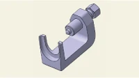
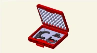
Special Service Tool
| Tool Name / Number | Illustration | Description |
|
Ball joint puller 09568 - 2J100 |
|
Used for removal of tie rod end |
|
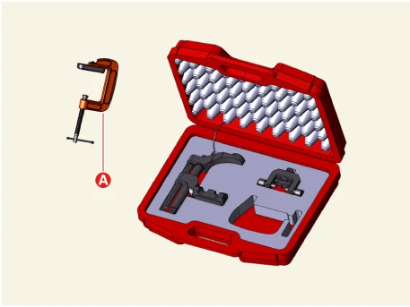
Lower arm ball joint remover 0K545 - A9100 |
|
Used for removal of front lower arm ball joint |
Removal

• When working on high voltage system, the work should be performed by technicians who have completed the relevant training. It is because that lack of knowledge of the high voltage system can lead to serious accidents due to electric shock or electric leakage.
• When working on high voltage system or related system, make sure that you are familiar and comply with the "Safety Precautions, Cautions and Warnings." If you do not comply with the instructions, serious accidents due to electric shock or leakage may occur.
• When working on high voltage system, make sure to check the Personal Protective Equipment (PPE) and high voltage shut-off procedures.
1.Align the steering wheel straight.
2.Turn the IG to 'OFF'.
3.Disconnect the battery negative ( - ) terminal and the service interlock connector.(Refer to Battery Control System - "Auxiliary 12 V Battery - 2WD")
4.Secure the steering wheel to prevent movement.

5.Remove the front trunk.(Refer to Body - "Front Trunk")
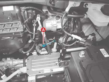
6.Separate the steering universal joint from the steering gear box.
(1)Remove the steering universal joint bolt (A).
Tightening torque :49 - 58.8 N·m (5.0 - 6.0 kgf·m, 36.2 - 43.4 lb·ft)

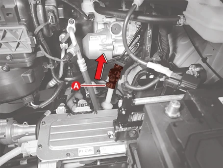
(2)Separate the steering universal joint (A) in the direction of the arrow.
7.Separate the air conditioning compressor.
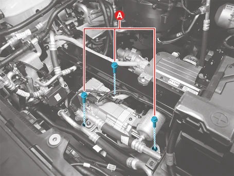
(1)Remove the air conditioning compressor bolts (A).
Tightening torque :16.7 - 23.5 N·m (2.0 - 2.4 kgf·m, 14.5 - 17.3 lb·ft)
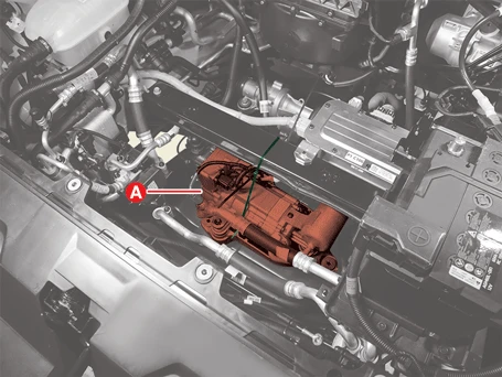
(2)Hold the air conditioning compressor (A) on the body using a cable tie.
8.Remove the front under cover.(Refer to Motor and Reduction Gear System - "Front Under Cover")
9.Remove the front wheel and tires.(Refer to Tires/Wheels - "Wheel")
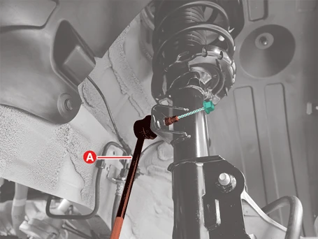
10.Remove the stabilizer bar link (A) from the front strut assembly after removing the nut.
Tightening torque :98.1 - 117.7 N·m (10.0 - 12.0 kgf·m, 72.3 - 86.8 lb·ft)

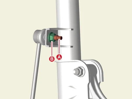
• Hold the outer hex (A) when removing or installing the nut (B).
• Be careful not to damage the boot of the link.
• Use a hand tool when removing or installing the stabilizer bar link nut.
11.Separate the lower arm ball joint from the front axle using SST (0K545 - A9100).
(1)Remove the split pin (D).
(2)Remove the lower arm bolt (A), washer (B), and nut (C).
Tightening torque :98.1 - 117.7 N·m (10.0 - 12.0 kgf·m, 72.3 - 86.8 lb·ft)
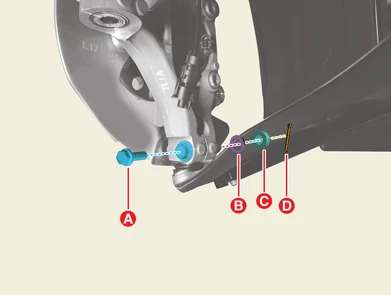


• Do not reuse the split pin.
• Be careful not to change the position of the bolt, nut, and washer when installing.
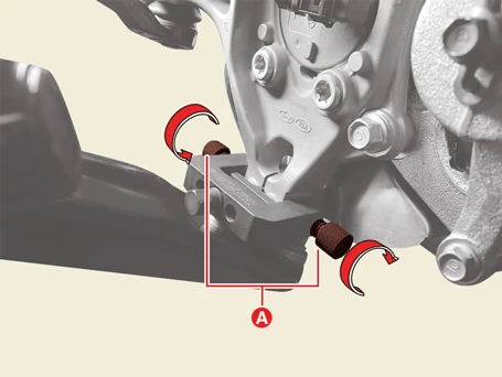
(3)Place the support bolts (A) to the lower arm ball joint mounting hole, and then rotate them to install the SST.

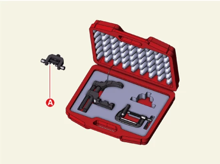
(4)Install the support body (B) in the front axle groove (A).
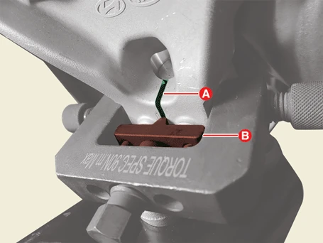
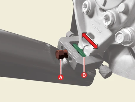
(5)Rotate the bolt (A) to insert the support body (B) to release the front knuckle.
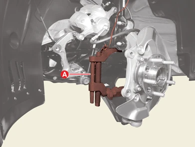
(6)Install the main body (A) between the front strut assembly and front lower arm.

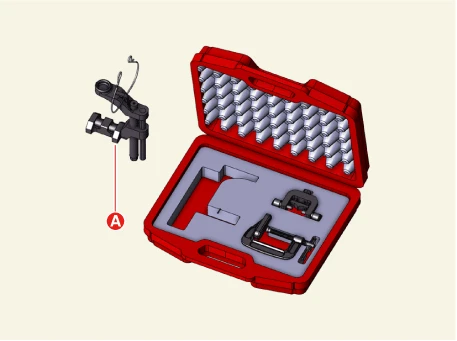
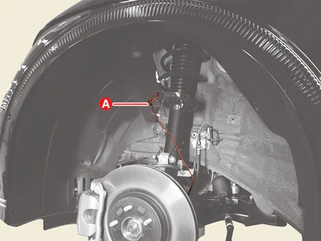
(7)Secure the main body with the wire (A) to prevent it from falling.
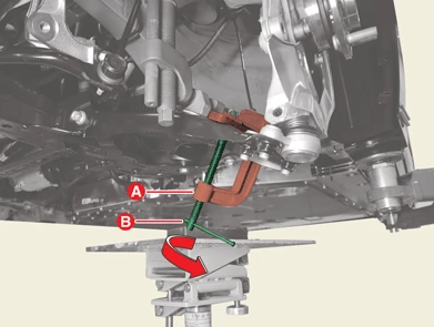
(8)Install the c-clamp (A) by rotating the handle (B) to prevent the main body from slipping.

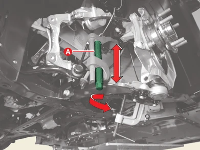
(9)Tighten the bolt (A) to widen the gap of the main body so that the front lower arm can be removed from the front knuckle.
12.Separate the tie rod end ball joint from the front axle.
(1)Remove the split pin (A).
(2)Remove the lock nut (B), and washer (C).
Tightening torque :98.1 - 117.7 N·m (10.0 - 12.0 kgf·m, 72.3 - 86.8 lb·ft)
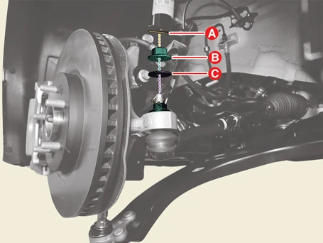

• Do not reuse the split pin.
• Do not reuse the lock nut.
• Be careful not to damage the boot of the link.
• Use a hand tool when removing or installing the lock nut.
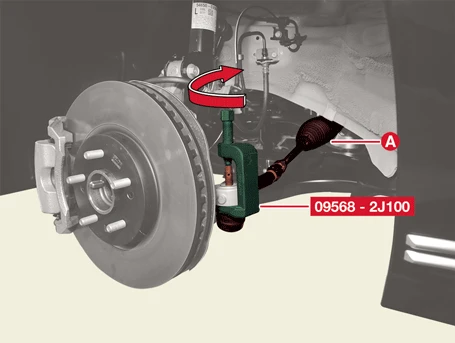
(3)Separate the tie rod end (A) using SST (09568 - 2J100).
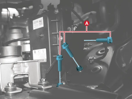
13.Remove the PTC heater bolts (A).
Tightening torque :6.9 - 10.8 N·m (0.7 - 1.1 kgf·m, 5.1 - 8 lb·ft)
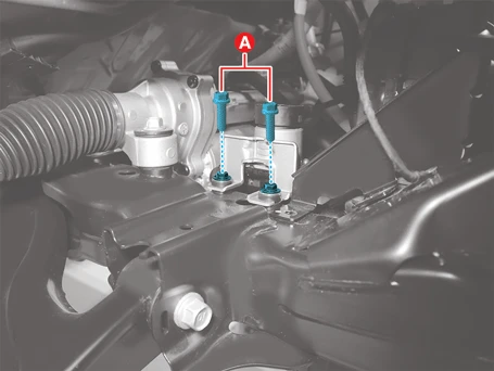
14.Remove the 3-way valve bolts (A).
Tightening torque :6.9 - 10.8 N·m (0.7 - 1.1 kgf·m, 5.1 - 8 lb·ft)
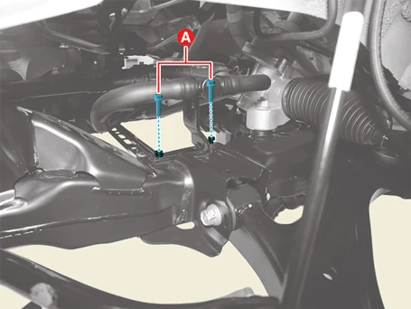
15.Remove the distribution pipe bracket bolts (A).
Tightening torque :6.9 - 10.8 N·m (0.7 - 1.1 kgf·m, 5.1 - 8 lb·ft)
16.Remove the battery EWP bolts (A) and nut (B).
Tightening torque :6.9 - 10.8 N·m (0.7 - 1.1 kgf·m, 5.1 - 8 lb·ft)
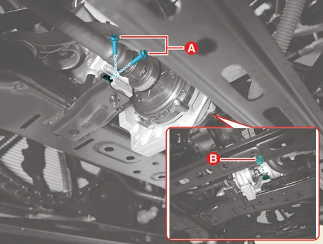
17.Disconnect the MDPS power pack connectors.
(1)Pull the connector keys (A) in the direction of the arrow.
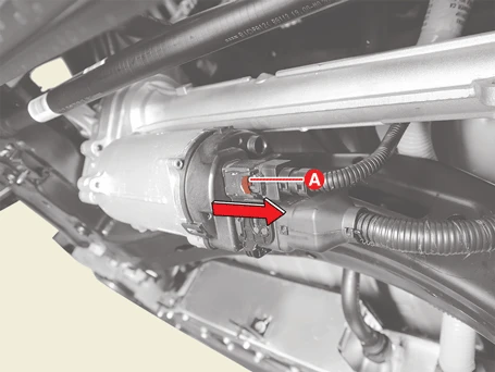
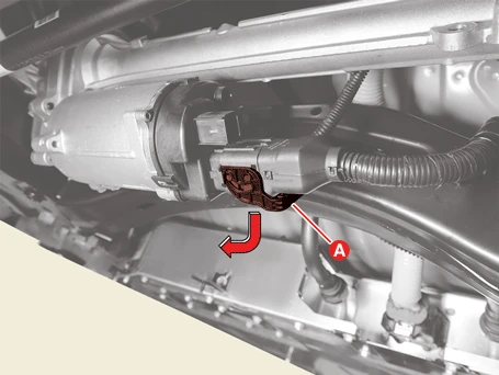
(2)Disconnect the connectors (A).
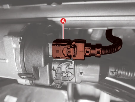
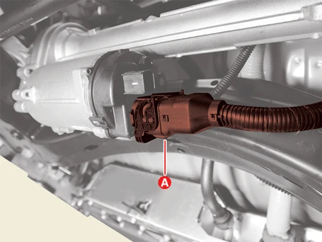
18.Remove the ground cables (A) after removing the bolts.
Tightening torque :6.9 - 10.8 N·m (0.7 - 1.1 kgf·m, 5.1 - 8 lb·ft)
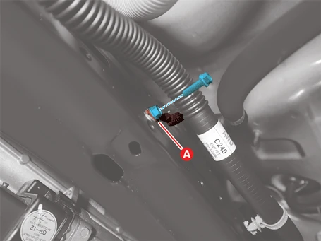
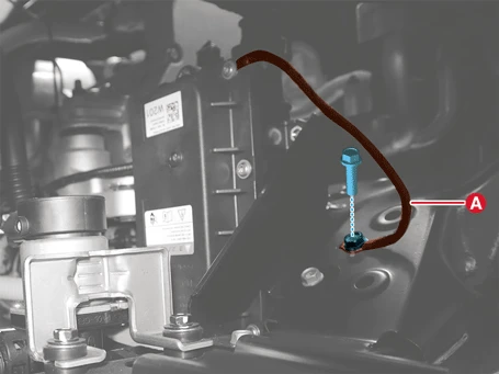
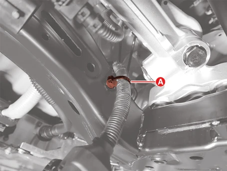
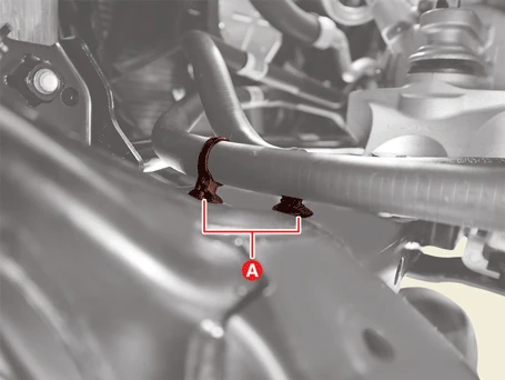
19.Remove the wiring clips (A) on the front sub frame.
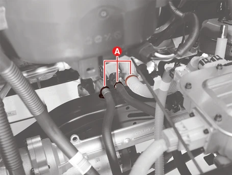
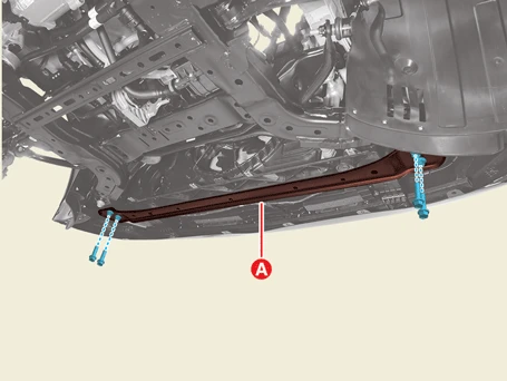
20.Remove the front sub frame bar (A) after removing the bolts.
Tightening torque :166.7 - 186.3 N·m (17.0 - 19.0 kgf·m, 123 - 137.4 lb·ft)
21.Support the front sub frame with the table lift (A) securely.
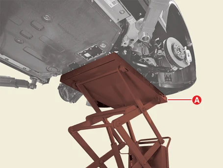


• When installing or removing the front subframe stay bolts and nuts, adjust the table lift position to make a workspace.
• Place the rubber block (A) between the front sub frame and table lift to maintain level.
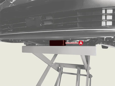
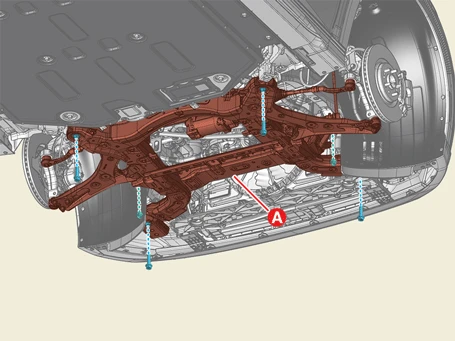
22.Remove the bolts and nuts, and then lower the table lift slowly to remove the front sub frame (A).
Tightening torque :176.5 - 196.1 N·m (18.0 - 20.0 kgf·m, 130.2 - 144.7 lb·ft)
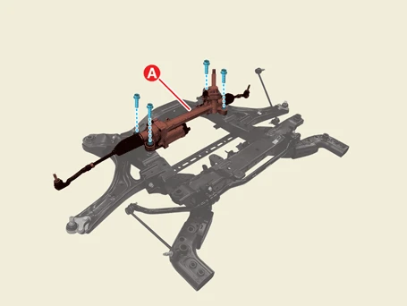
23.Remove the steering gear box (A) after removing the bolts.
Tightening torque :107.9 - 127.5 N·m (11.0 - 13.0 kgf·m, 79.6 - 94.0 lb·ft)

24.Remove the front lower arm (A) after removing the bolts (B,C), nuts, and washers.
Tightening torque :156.9 - 176.5 N·m (16.0 - 18.0 kgf·m, 115.7 - 130.2 lb·ft)
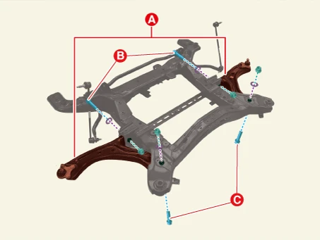
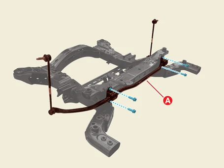
25.Remove the front stabilizer bar (A) after removing the bolts.
Tightening torque :49.0 - 63.7 N·m (5.0 - 6.5 kgf·m, 36.2 - 47.0 lb·ft)
Installation
1.Install in the reverse order of removal.
2.Check the alignment.(Refer to Alignment - "Repair Procedures")
Removal

• When working on high voltage system, the work should be performed by technicians who have completed the relevant training. It is because that lack of knowledge of the high voltage system can lead to serious accidents due to electric shock or electric leakage.
• When working on high voltage system or related system, make sure that you are familiar and comply with the "Safety Precautions, Cautions and Warnings." If you do not comply with the instructions, serious accidents due to electric shock or leakage may occur.
• When working on high voltage system, make sure to check the Personal Protective Equipment (PPE) and high voltage shut-off procedures.
1.Remove the front motor and reduction gear assembly.(Refer to Front Motor and Reduction Gear System - "Front Motor and Reduction Gear Assembly")
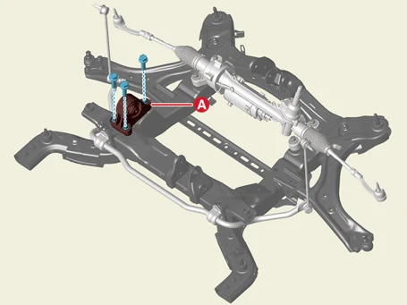
2.Remove the mounting bracket (A) after removing the bolts.
Tightening torque :63.7 - 83.4 N·m (6.5 - 8.5 kgf·m, 47.0 - 61.5 lb·ft)
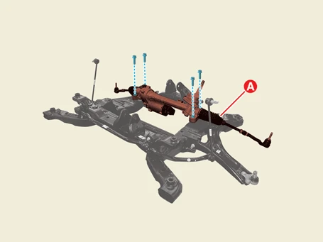
3.Remove the steering gear box (A) after removing the bolts.
Tightening torque :107.9 - 127.5 N·m (11.0 - 13.0 kgf·m, 79.6 - 94.0 lb·ft)

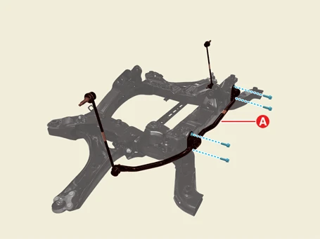
4.Remove the front stabilizer bar (A) after removing the bolts.
Tightening torque :49.0 - 63.7 N·m (5.0 - 6.5 kgf·m, 36.2 - 47.0 lb·ft)
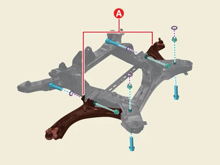
5.Remove the front lower arm (A) after removing the bolts, nuts, and washers.
Tightening torque :156.9 - 176.5 N·m (16.0 - 18.0 kgf·m, 115.7 - 130.2 lb·ft)
Installation
1.Install in the reverse order of removal.
2.Check the alignment.(Refer to Alignment - "Repair Procedures")
