Description
It is mounted on the active air flap (AAF) and senses the temperature of the outside air. It is a NTC thermistor type in which the resistance value decreases when the temperature rises and the resistance value increases when the temperature decreases.It is used for discharge temperature control, sensor compensation, temperature control door control, blower motor speed control, mix mode control, and in-vehicle humidity control.Removal

• When working on high voltage system, the work should be performed by technicians who have completed the relevant training. A lack of understanding of the high voltage system can lead to serious accidents due to electric shock or electric leakage.
• When working a high voltage system, the technician must be observed and aware of "High Voltage System General Safety Information and Caution". If not, it may cause serious accidents such as electric shock or short circuit.
• When working on high voltage system, make sure to check the Personal Protective Equipment (PPE) and high voltage shut-off procedures.
1.Disconnect the battery negative ( - ) terminal and the service interlock connector.(Refer to Battery Control System - "Auxiliary 12 V Battery - 2WD")(Refer to Battery Control System - "Auxiliary 12 V Battery - 4WD")
2.Remove the Active Air Flap (AAF).(Refer to Cooling System - "Active Air Flap (AAF)")
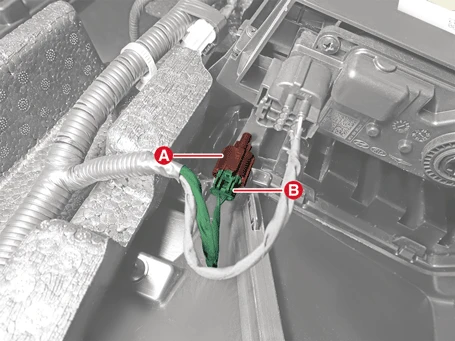
3.Remove the ambient temperature sensor (A) after disconnecting the ambient temperature sensor connector (B).

Installation

• When working on high voltage system, the work should be performed by technicians who have completed the relevant training. A lack of understanding of the high voltage system can lead to serious accidents due to electric shock or electric leakage.
• When working a high voltage system, the technician must be observed and aware of "High Voltage System General Safety Information and Caution". If not, it may cause serious accidents such as electric shock or short circuit.
• When working on high voltage system, make sure to check the Personal Protective Equipment (PPE) and high voltage shut-off procedures.
1.Install in reverse order of removal.
Inspection
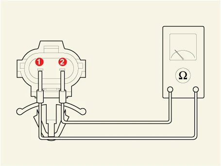
1.Check whether the resistance values of terminals 1 and 2 change by applying the temperature change of the air to the outside temperature sensor.

1. Ambient Sensor ( + )
2. Sensor Ground
Sensor resistance
| Temperature [°C (°F)] | Resistance (kΩ) |
| -30 (-22) | 480.41 |
| -20 (-4) | 271.21 |
| -10 (14) | 158.18 |
| 0 (32) | 95.10 |
| 10 (50) | 58.80 |
| 20 (68) | 37.32 |
| 30 (86) | 24.26 |
| 40 (104) | 16.13 |
| 50 (122) | 10.95 |