Description
The intake actuator is mounted on the blower unit and adjusts the intake door according to the signal from the control unit.Press the recirculation/fresh air select switch to switch to recirculation or fresh air intake mode.Removal

• When working on high voltage system, the work should be carried by technicians who have completed the relevant training. A lack of understanding of the high voltage system can lead to serious accidents due to electric shock or electric leakage.
• When working a high voltage system, the technician must be observed and aware of "High Voltage System General Safety Information and Caution". If not, it may cause serious accidents such as electric shock or short circuit.
• When working on high voltage system, make sure to check the Personal Protective Equipment (PPE) and high voltage shut-off procedures.
1.Disconnect the battery negative ( - ) terminal and the service interlock connector.(Refer to Battery Control System - "Auxiliary 12 V Battery - 2WD")(Refer to Battery Control System - "Auxiliary 12 V Battery - 4WD")
2.Remove the blower unit.(Refer to Heating, Ventilation and Air conditioning - "Blower Unit")
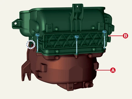
3.Separate the upper blower unit (B) and lower blower unit (A) after removing the screws.
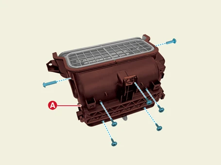
4.Remove the blower unit upper cover (A) after removing the screws.
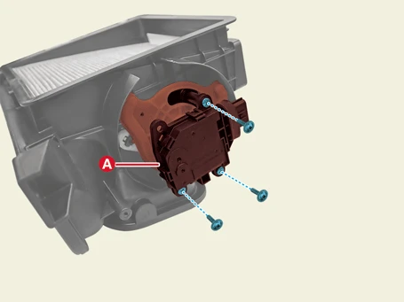
5.Remove the intake actuator (A) after removing the screws.
Installation

• When working on high voltage system, the work should be carried by technicians who have completed the relevant training. A lack of understanding of the high voltage system can lead to serious accidents due to electric shock or electric leakage.
• When working a high voltage system, the technician must be observed and aware of "High Voltage System General Safety Information and Caution". If not, it may cause serious accidents such as electric shock or short circuit.
• When working on high voltage system, make sure to check the Personal Protective Equipment (PPE) and high voltage shut-off procedures.
1.Install in reverse order of removal.
Removal

• When working on high voltage system, the work should be carried by technicians who have completed the relevant training. A lack of understanding of the high voltage system can lead to serious accidents due to electric shock or electric leakage.
• When working a high voltage system, the technician must be observed and aware of "High Voltage System General Safety Information and Caution". If not, it may cause serious accidents such as electric shock or short circuit.
• When working on high voltage system, make sure to check the Personal Protective Equipment (PPE) and high voltage shut-off procedures.
1.Shut off the high voltage circuit.(Refer to Heating, Ventilation and Air Conditioning - "High Voltage Shut off Procedure")
2.Remove the front high voltage junction box.(Refer to Battery Control System - "Front High Voltage Junction Box")
3.Disconnect the intake actuator connector (A) after removing the clip (B).
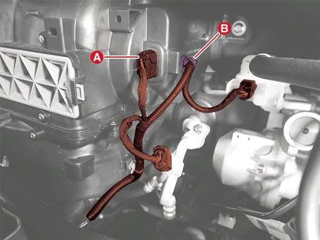
4.Remove the blower unit screws (A).
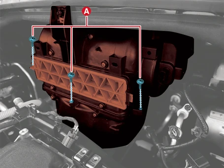
5.Remove the upper blower unit (A) after removing the nuts.
Tightening torque :7.8 - 11.8 N·m (0.8 - 1.2 kgf·m, 5.8 - 8.7 lb·ft)
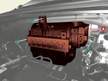
6.Remove the blower unit upper cover (A) after removing the screws.
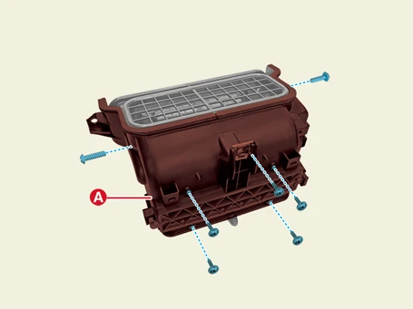
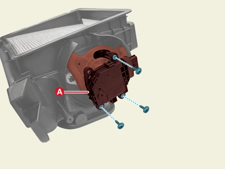
7.Remove the intake actuator (A) after removing the screws.
Installation

• When working on high voltage system, the work should be carried by technicians who have completed the relevant training. A lack of understanding of the high voltage system can lead to serious accidents due to electric shock or electric leakage.
• When working a high voltage system, the technician must be observed and aware of "High Voltage System General Safety Information and Caution". If not, it may cause serious accidents such as electric shock or short circuit.
• When working on high voltage system, make sure to check the Personal Protective Equipment (PPE) and high voltage shut-off procedures.
1.Install in reverse order of removal.
Inspection
1.Turn IG OFF.
2.Disconnect the intake actuator connector.
3.Check if the actuator is operating by connecting the power ( + ) terminal to the 6th terminal of the intake switching actuator connector and the ( - ) terminal to the 4th terminal. When connected in the opposite direction, check if it operates in reverse.
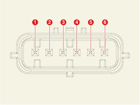
1. Recirculated Air
2. Fresh Air
3. -
4. Sensor Ground
5. Feedback Signal
6. Sensor Power (+5 V)
4.Connect the intake actuator connector.
5.Turn IG ON.
6.Measure the voltage across terminals 1 - 2.
| Door position | Voltage (V) | Error detection |
| 0 ° | 0.5 ± 0.15 |
Low voltage : less than 0.1 V High voltage : more than 4.9 V |
| 80 ° | 4.5 ± 0.15 |
7.If the measured voltage does not match with the specification, replace it with a new intake actuator.