Specification
| Item | Specification |
| Input voltage (V) | 452.5 - 778.3 |
| Operating voltage (V) | 9 - 16 |
| Continuous current (A) | 75 (@20 min.) |
| Ampere (A) | Maximum 190 (@15 sec.) |
Component
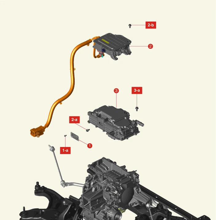
1. High Voltage Junction Box Service Cover
1-a. 3.9 - 5.9 N·m (0.4 - 0.6 kgf·m, 2.9 - 4.3 lb·ft, 34.7 - 52.1 lb·in)
2. Front High Voltage Junction Box
2-a. 6.9 - 9.8 N·m (0.7 - 1.0 kgf·m, 5.1 - 7.2 lb·ft)
2-b. 6.9 - 9.8 N·m (0.7 - 1.0 kgf·m, 5.1 - 7.2 lb·ft)
3. Inverter Assembly
3-a. 3.9 - 5.9 N·m (0.4 - 0.6 kgf·m, 2.9 - 4.3 lb·ft, 34.7 - 52.1 lb·in)
Description
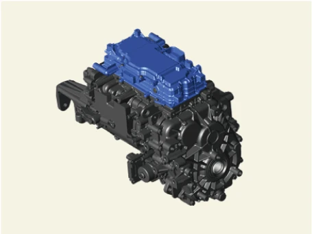
• It is installed in the front motor and converts the DC power to the AC power(variable frequency and voltage).
• It controls the rotational speed and torque of the motor through the power control.
Removal

• When working on high voltage system, the work should be performed by technicians who have completed the relevant training. A lack of understanding of the high voltage system can lead to serious accidents due to electric shock or electric leakage.
• When working on high voltage system or related components, make sure that you are familiar and comply with the "Safety Precautions, Cautions and Warnings." If you do not comply with the instructions, serious accidents due to electric shock or leakage may occur.
• When working on high voltage system, make sure to check the Personal Protective Equipment (PPE) and high voltage shut-off procedures.
1.Drain the motor coolant.(Refer to Cooling System - "Coolant")
2.Remove the front high voltage junction box.(Refer to High Voltage Distributing System - "Front High Voltage Junction Box")
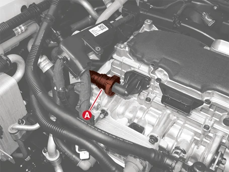
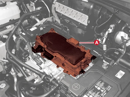
3.Separate the inverter cooling quick connector hose (A).
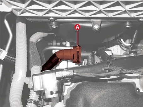
4.Remove the inverter assembly (A) after removing the bolts.
Tightening torque :3.9 - 5.9 N·m (0.4 - 0.6 kgf·m, 2.9 - 4.3 lb·ft, 34.7 - 52.1 lb·in)
Installation

• When working on high voltage system, the work should be performed by technicians who have completed the relevant training. A lack of understanding of the high voltage system can lead to serious accidents due to electric shock or electric leakage.
• When working on high voltage system or related components, make sure that you are familiar and comply with the "Safety Precautions, Cautions and Warnings." If you do not comply with the instructions, serious accidents due to electric shock or leakage may occur.
• When working on high voltage system, make sure to check the Personal Protective Equipment (PPE) and high voltage shut-off procedures.
1.Install in the reverse order of removal.

• Install the inverter assembly to the specified torque.
• If the inverter assembly is dropped, it may cause internal damage. (Do not reuse)
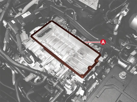
• Replace the gasket (A) and check the installation before installing the inverter assembly.
2.Perform the PE system leak test with the KDS.(Refer to High Voltage Distributing System - "Front High Voltage Junction Box")
3.Fill the motor coolant.(Refer to Cooling System - "Coolant")
4.Perform the Initialization of Automatic Resolver Offset Calibration procedures with the KDS.(S/W Management → Motor Control Unit-Front → Initialization of Automatic Resolver Offset Calibration)
