Component
Upper Case
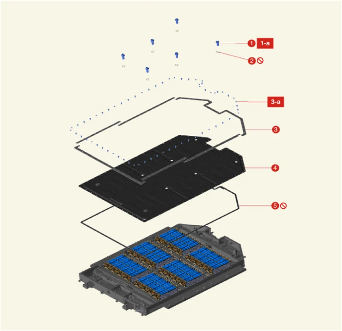
1. Upper Case Bolt
1-a. 103.0 - 154.9 N·m (10.5 - 15.8 kgf·m, 75.9 - 114.3 lb·ft)
2. O-ring
3. Watertight Bracket
3-a. 1st : 8.8 N·m (0.9 kgf·m, 6.5 lb·ft)
3-a. 2nd : 10.8 N·m (1.1 kgf·m, 8.0 lb·ft)
4. Upper Case
5. Waterproof Gasket
Lower Case
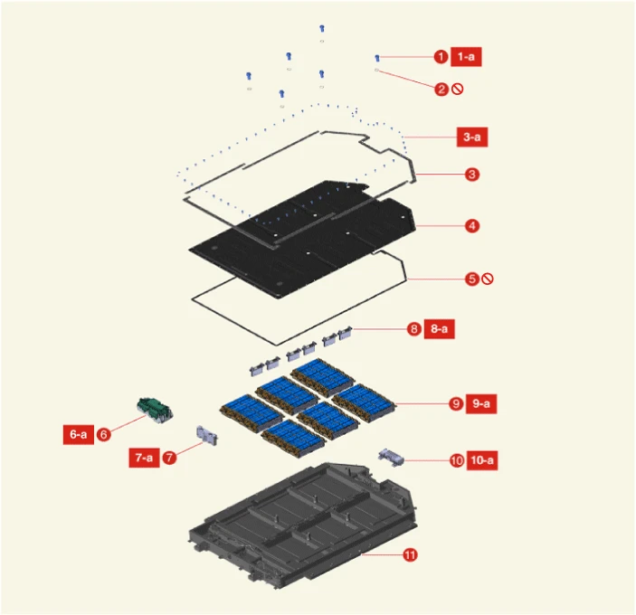
1. Upper Case Bolt
1-a. 103.0 - 154.9 N·m (10.5 - 15.8 kgf·m, 75.9 - 114.3 lb·ft)
2. O-ring
3. Watertight Bracket
3-a. 1st : 8.8 N·m (0.9 kgf·m, 6.5 lb·ft)
3-a. 2nd : 10.8 N·m (1.1 kgf·m, 8.0 lb·ft)
4. Upper Case
5. Waterproof Gasket
6. Power Relay Assembly (PRA)
6-a. 7.8 - 11.8 N·m (0.8 - 1.2 kgf·m, 5.8 - 8.7 lb·ft)
7. Battery Management Unit (BMU)
7-a. 1st : 8.8 N·m (0.9 kgf·m, 6.5 lb·ft)
7-b. 2nd : 10.8 N·m (1.1 kgf·m, 8.0 lb·ft)
8. Cell Monitoring Unit (CMU)
8-a. 1st : 8.8 N·m (0.9 kgf·m, 6.5 lb·ft)
8-b. 2nd : 10.8 N·m (1.1 kgf·m, 8.0 lb·ft)
9. Battery Module Assembly (BMA)
9-a. 7.8 - 11.8 N·m (0.8 - 1.2 kgf·m, 5.8 - 8.7 lb·ft)
10. Main Fuse
10-a. 7.8 - 11.8 N·m (0.8 - 1.2 kgf·m, 5.8 - 8.7 lb·ft)
11. Lower Case
Removal

• When working on high voltage system, the work should be performed by technicians who have completed the relevant training. A lack of understanding of the high voltage system can lead to serious accidents due to electric shock or electric leakage.
• When working on high voltage system or related components, make sure that you are familiar and comply with the "Safety Precautions, Cautions and Warnings." If you do not comply with the instructions, serious accidents due to electric shock or leakage may occur.
• When working on high voltage system, make sure to check the Personal Protective Equipment (PPE) and high voltage shut-off procedures.

• After the accident, check high voltage battery sensor data (insulation resistance, voltage deviation between cells, DTC, etc.) and check for internal damage.
• When only the high voltage battery case is replaced due to fine deformation, only the case is replaced after checking the change in the high voltage battery sensor data.
• Perform the air tightness inspection with the KDS after repairing the battery.
• If the battery system assembly (BSA) is not sealed and there is a leak in the cooling water line, it may cause serious failure of the BSA.
Upper Case
1.Remove the Battery System Assembly (BSA).(Refer to High Voltage Battery System - "Battery System Assembly (BSA)")
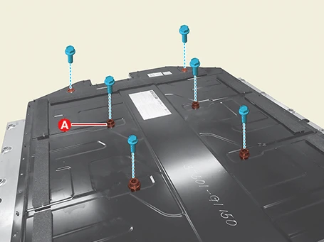
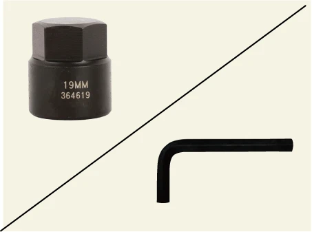
2.Remove the high voltage battery system upper case bolts (A).
Tightening torque :103.0 - 154.9 N·m (10.5 - 15.8 kgf·m, 75.9 - 114.3 lb·ft)

3.Remove the watertight brackets (A) after removing the bolts and nuts.
Tightening torque1st : 8.8 N·m (0.9 kgf·m, 6.5 lb·ft)2nd : 10.8 N·m (1.1 kgf·m, 8.0 lb·ft)
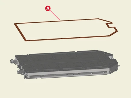
4.Remove the high voltage battery system upper case (A).
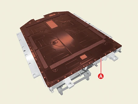

• When removing the upper case to prevent deformation, work with at least two people.
• Recommend to transfer with the horizontal side rather than the longitudinal due to cause transformed in the case of removing the case asymmetrically or pressing the load momentarily.
Lower Case
1.Remove the Battery Management Unit (BMU).(Refer to High Voltage Battery Control System - "Battery Management Unit (BMU)")
2.Remove the main fuse.(Refer to High Voltage Battery Control System - "Main Fuse")
3.Remove the Battery System Assembly (BSA).(Refer to High Voltage Battery System - "Battery System Assembly (BSA)")
4.Remove the Battery System Assembly (BSA) upper case.(Refer to Case - "Removal and Installation")
5.Remove the Power Relay Assembly (PRA).(Refer to High Voltage Battery Control System - "Power Relay Assembly (PRA)")
6.Remove the Cell Monitoring Unit (CMU).(Refer to High Voltage Battery Control System - "Cell Monitoring Unit (CMU)")
7.Remove the Battery Module Assembly (BMA).(Refer to High Voltage Battery System - "Battery Module Assembly (BMA)")
8.Remove the Integrated Charging Control Unit (ICCU) connector service cover (A) after removing the bolts.
Tightening torque :7.8 - 11.8 N·m (0.8 - 1.2 kgf·m, 5.8 - 8.7 lb·ft)
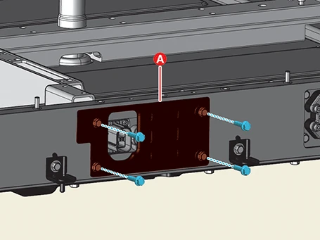
9.Remove the ICCU connector assembly (A) after removing the bolts.
Tightening torque :7.8 - 11.8 N·m (0.8 - 1.2 kgf·m, 5.8 - 8.7 lb·ft)
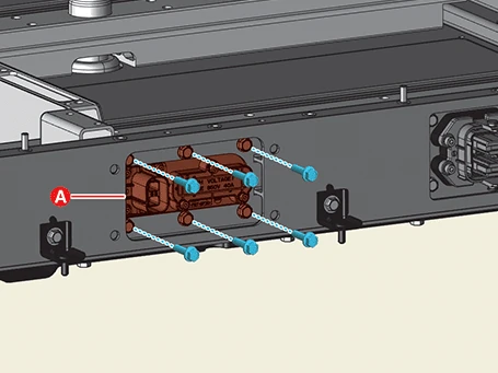
10.Remove the high voltage junction box connector assembly (A) after removing the bolts.
Tightening torque :7.8 - 11.8 N·m (0.8 - 1.2 kgf·m, 5.8 - 8.7 lb·ft)
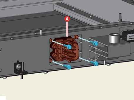
11.Remove the BMU connector assembly (A) after removing the bolts.
Tightening torque :7.8 - 11.8 N·m (0.8 - 1.2 kgf·m, 5.8 - 8.7 lb·ft)
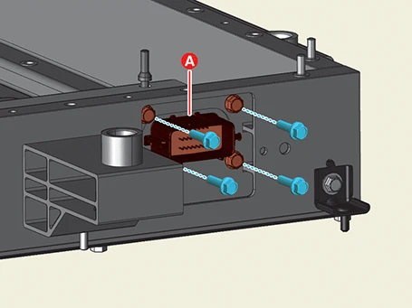
12.Remove the front high voltage junction box connector assembly (A) after removing the bolts.
Tightening torque :7.8 - 11.8 N·m (0.8 - 1.2 kgf·m, 5.8 - 8.7 lb·ft)
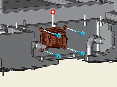
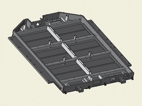
13.Remove the lower case.
Installation

• When working on high voltage system, the work should be performed by technicians who have completed the relevant training. A lack of understanding of the high voltage system can lead to serious accidents due to electric shock or electric leakage.
• When working on high voltage system or related components, make sure that you are familiar and comply with the "Safety Precautions, Cautions and Warnings." If you do not comply with the instructions, serious accidents due to electric shock or leakage may occur.
• When working on high voltage system, make sure to check the Personal Protective Equipment (PPE) and high voltage shut-off procedures.
1.Apply a new gap filler using the tools.(Refer to High Voltage Battery System - "Gap Filler Application")
2.Perform the High Voltage Battery Pack Connector Check with the KDS before installing the Battery System Assembly (BSA) upper case.(S/W Management → Battery Management System (BMS) → High Voltage Battery Pack Connector Check)

3.Install in the reverse order of removal.

• Install the case to the specified torque.
• In order to maintain the integrity of the Battery System Assembly (BSA), replace the case if any deformation occurs.
• When removing the upper case to prevent deformation, work with at least two people.
• Recommend to transfer with the horizontal side rather than the longitudinal due to cause transformed in the case of removing the case asymmetrically or pressing the load momentarily.
• The upper case bolts (A) are different, so check the shape and tighten them to the correct position.
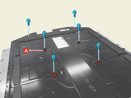
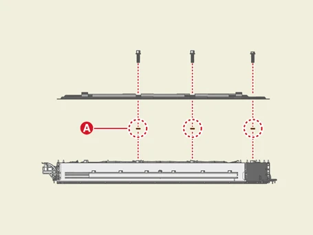
• The existing O-rings (A) of the upper case bolt should be replaced with new ones (Do not reuse).
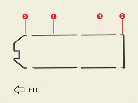
• Install the watertight bracket in the following order below.
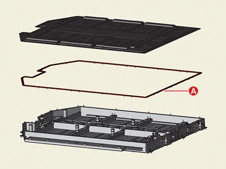
• The existing gasket (A) of the upper case should be replaced with new one (do not reuse).
4.Perform the air tightness inspection with the KDS.(Refer to High Voltage Battery System - "Air Tightness Inspection")