Removal
1.Remove the front wheel and tires.(Refer to Suspension System - "Wheel")
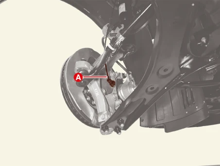
2.Disconnect the front wheel speed sensor connector (A).
3.Remove the front brake disc.(Refer to Brake System - "Front Brake Disc")
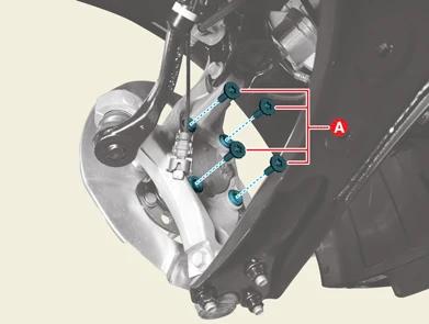
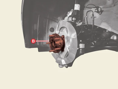
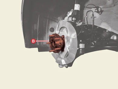
4. Remove the front hub assembly (B) after removing the front hub assembly bolts (A).
Tightening torque :127.5 - 147.1 N·m (13.0 - 15.0 kgf·m, 94.0 - 108.5 lb·ft)
Installation
1.Install in the reverse order of removal.
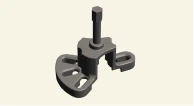
Special Service Tool
| Tool Name / Number | Illustration | Description |
|
CV joint puller 09517 - 4E000 |
|
Used for removal of CV joint |
Removal
1.Remove the front wheel and tires.(Refer to Suspension System - "Wheel")
2.Unlock the driveshaft lock nut caulking (A), by hammering on a chisel or suitable tool.
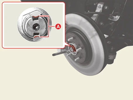
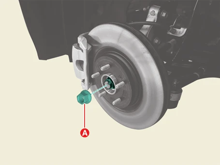
3.Remove the driveshaft lock nut (A).
Tightening torque :294.2 - 313.8 N·m (30.0 - 32.0 kgf·m, 217 - 231.5 lb·ft)
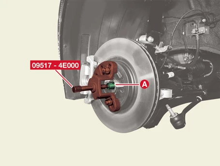
4.Separate the front driveshaft (A) from the front axle by using the SST (09517 - 4E000).
5.Remove the front brake disc.(Refer to Brake System - "Front Brake Disc")
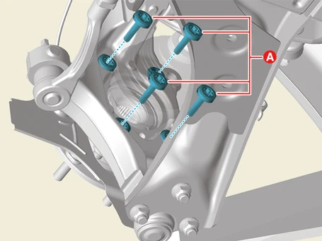
6. Remove the front hub assembly (B) after removing the front hub assembly bolts (A).
Tightening torque :127.5 - 147.1 N·m (13.0 - 15.0 kgf·m, 94.0 - 108.5 lb·ft)
Installation
1.Install in the reverse order of removal.

• Do not reuse the driveshaft lock nut.
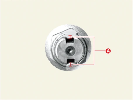
• After tightening the driveshaft lock nut, caulk the lock nut to an appropriate depth (A) by using a chisel or suitable tool.
Caulking Depth (A) :1.5 mm (0.0590 in.) or more
• Press the brake pedal to prevent the driveshaft from rotating when tightening the driveshaft lock nut.
Inspection
1.Check the hub for cracks and spline wear.
2.Check the hub bearing for defects.
