Special Service Tool
| Tool Name / Number | Illustration | Description |
|
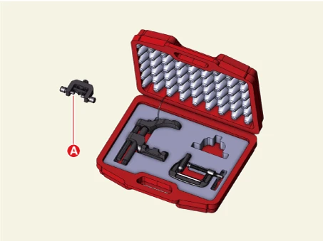
Lower arm ball joint remover 0K545 - A9100 |
|
Used for removal of front lower arm ball joint |
Removal
[Front Lower Arm Ball Joint]
1.Remove the front wheel and tires.(Refer to Tires/Wheels - "Wheel")
2.Remove the front under cover.(Refer to Motor and Reduction Gear System - "Front Under Cover")
3.Separate the lower arm ball joint from the front axle using SST (0K545 - A9100).
(1)Remove the split pin (D).
(2)Remove the lower arm bolt (A), washer (B), and nut (C).
Tightening torque :98.1 - 117.7 N·m (10.0 - 12.0 kgf·m, 72.3 - 86.8 lb·ft)
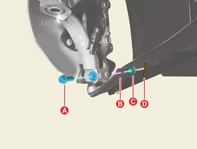


• Do not reuse the split pin.
• Be careful not to change the position of the bolt, nut, and washer when installing.
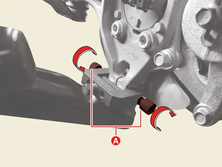
(3)Place the support bolts (A) to the lower arm ball joint mounting hole, and then rotate them to install the SST.

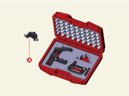
(4)Install the support body (B) in the front axle groove (A).
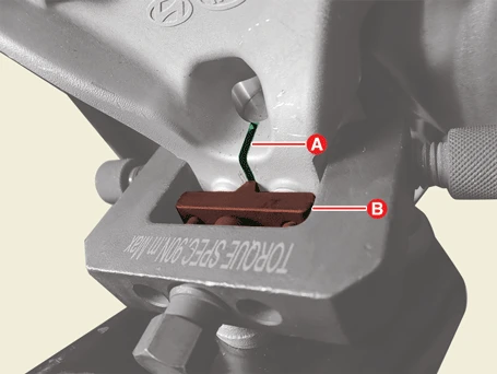
(5)Rotate the bolt (A) to insert the support body (B) to release the front knuckle.
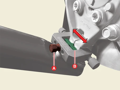
(6)Install the main body (A) between the front strut assembly and front lower arm.
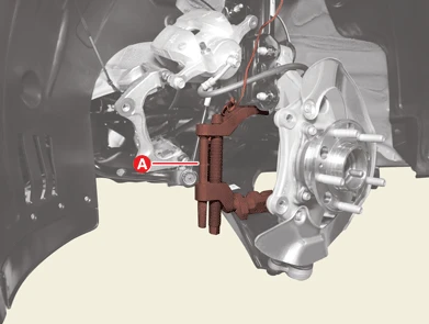

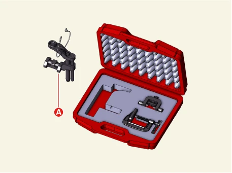
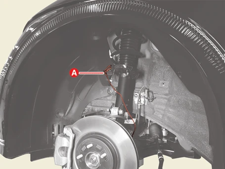
(7)Secure the main body with the wire (A) to prevent it from falling.
(8)Install the c-clamp (A) by rotating the handle (B) to prevent the main body from slipping.
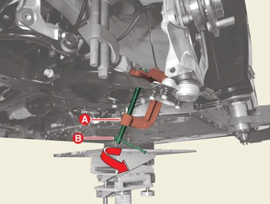

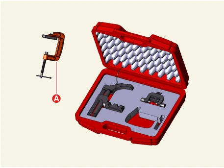
(9)Tighten the bolt (A) to widen the gap of the main body so that the front lower arm can be removed from the front knuckle.
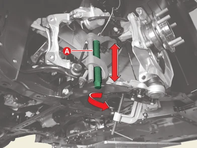
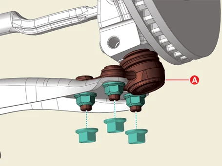
4.Remove the lower arm ball joint (A) after removing the nuts.
Tightening torque :98.1 - 117.7 N·m (10.0 - 12.0 kgf·m, 72.3 - 86.8 lb·ft)
[Front Lower Arm Assembly]
1.Remove the front wheel and tires.(Refer to Tires/Wheels - "Wheel")
2.Separate the lower arm ball joint from the front axle using SST (0K545 - A9100).
(1)Remove the split pin (D).
(2)Remove the lower arm bolt (A), washer (B), and nut (C).
Tightening torque :98.1 - 117.7 N·m (10.0 - 12.0 kgf·m, 72.3 - 86.8 lb·ft)
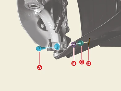


• Do not reuse the split pin.
• Be careful not to change the position of the bolt, nut, and washer when installing.
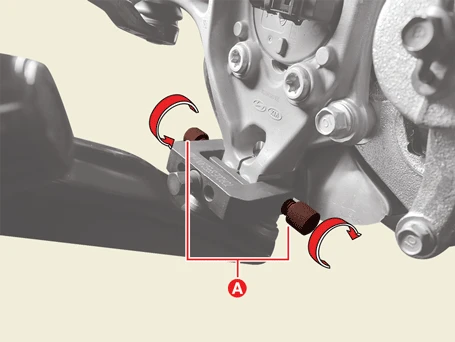
(3)Place the support bolts (A) to the lower arm ball joint mounting hole, and then rotate them to install the SST.

(4)Install the support body (B) in the front axle groove (A).
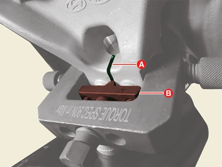
(5)Rotate the bolt (A) to insert the support body (B) to release the front knuckle.
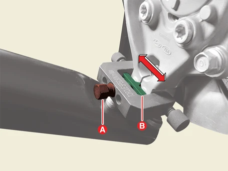
(6)Install the main body (A) between the front strut assembly and front lower arm.
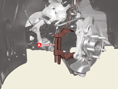

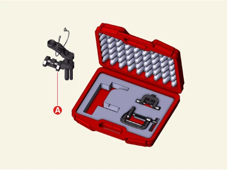
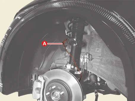
(7)Secure the main body with the wire (A) to prevent it from falling.
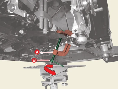
(8)Install the c-clamp (A) by rotating the handle (B) to prevent the main body from slipping.

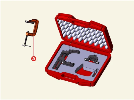
(9)Tighten the bolt (A) to widen the gap of the main body so that the front lower arm can be removed from the front knuckle.
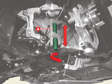
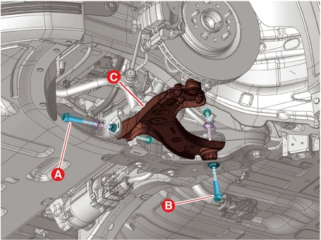
3.Remove the front lower arm (C) after removing the bolts, nut, and washer.
Tightening torque :(A) :117.7 - 137.3 N·m (12.0 - 14.0 kgf·m, 86.8 - 101.3 lb·ft)(B) :156.9 - 176.5 N·m (16.0 - 18.0 kgf·m, 115.7 - 130.2 lb·ft)
Installation
1.Install in the reverse order of removal.
2.Check the alignment.(Refer to Alignment - "Repair Procedures")
Inspection
1.Check the bushing for wear or aging.
2.Check the lower arm for bent or damaged.
3.Check all bolts.
