Components and Components Location
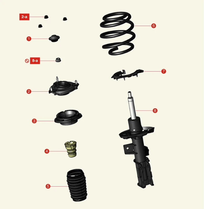
1. Insulator Cap
2. Insulator Assembly
2-a. 53.9 - 68.6 N·m (5.5 - 7.0 kgf·m, 39.8 - 50.6 lb·ft)
3. Strut Bearing
4. Bumper Stopper
5. Dust Cover
6. Coil Spring
7. Spring Lower Pad
8. Strut Assembly
8-a. 156.9 - 176.5 N·m (16.0 - 18.0 kgf·m, 115.7 - 130.2 lb·ft)
Removal
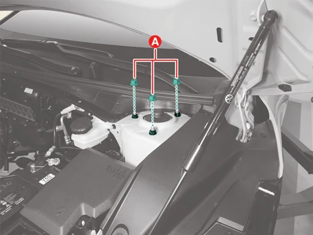
1.Remove the front strut upper mounting nuts (A).
Tightening torque :53.9 - 68.6 N·m (5.5 -7.0 kgf·m, 39.8 - 50.6 lb·ft)
2.Remove the front wheel and tires.(Refer to Tires/Wheels - "Wheel")
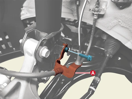
3.Remove the brake hose bracket (A) after removing the bolt.
Tightening torque :8.8 - 13.7 N·m (0.9 - 1.4 kgf·m, 6.5 - 10.1 lb·ft)
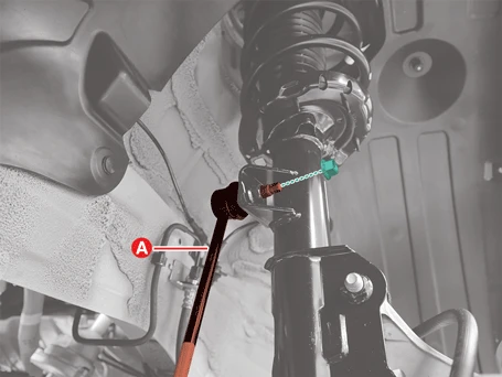
4.Remove the stabilizer bar link (A) from the front strut assembly after removing the nut.
Tightening torque :98.1 - 117.7 N·m (10.0 - 12.0 kgf·m, 72.3 - 86.8 lb·ft)

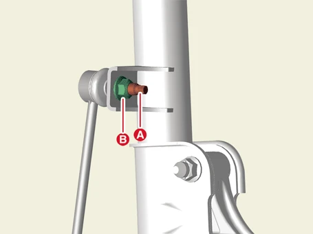
• Hold the outer hex (A) when removing or installing the nut (B).
• Be careful not to damage the boot of the link.
• Use a hand tool when removing or installing the stabilizer bar link nut.
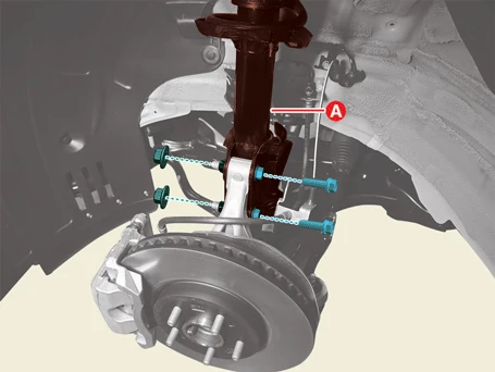
5.Remove the front strut assembly (A) from the front axle after removing the bolts and nuts.
Tightening torque :156.9 - 176.5 N·m (16.0 - 18.0 kgf·m, 115.7 - 130.2 lb·ft)
Installation
1.Install in the reverse order of removal.

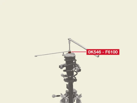
Special Service Tool
| Tool Name / Number | Illustration | Description |
|
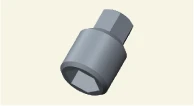
Shock absorber lock nut remover. 0K546 - F6100 |
|
Used for removal or installing of front strut lock nut. |
Disassembly
1.Remove the front strut assembly.(Refer to Front Suspension System - "Front Strut Assembly")
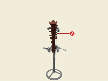
2.Install the front strut assembly (A) to the spring compressor.
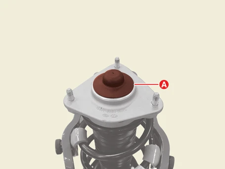
3.Remove the insulator cap (A).
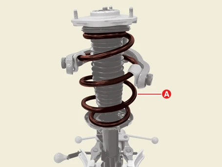
4.Compress the coil spring (A) slightly until it is tensioned using the spring compressor.

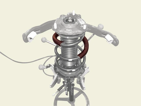
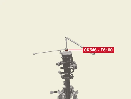
5.Remove the nut using the SST (0K546 - F6100).
Tightening torque :107.9 - 117.7 N·m (11.0 - 12.0 kgf·m, 79.6 - 86.8 lb·ft)
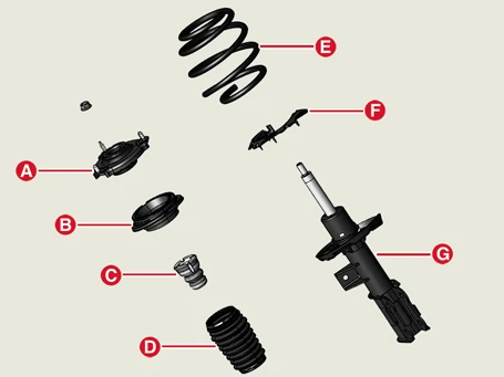
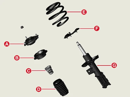
6.Disassemble insulator (A), strut bearing (B), bumper stopper (C), dust cover (D), coil spring (E), spring lower pad (F) from the strut (G).
Inspection
1.Check the strut insulator bearing for wear and damage.
2.Check the rubber parts for damage and deterioration.
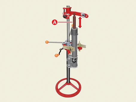
3.Compress and extend the piston rod (A) and check that there is no abnormal resistance or unusual sound during operation.
Disposal
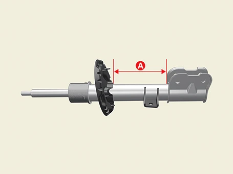
1.Fully extend the strut rod.
2.Drill a hole in the (A) area of the cylinder to deflate gas.

Special Service Tool
| Tool Name / Number | Illustration | Description |
|
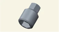
Shock absorber lock nut remover. 0K546 - F6100 |
|
Used for removal or installing of front strut lock nut |
Reassembly
1.Assemble the insulator (A), strut bearing (B), bumper stopper (C), dust cover (D), coil spring (E), and spring lower pad (F) on the strut (G).

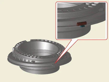
• Align the protrusions of the strut bearing upper housing and the lower housing when reassembling.
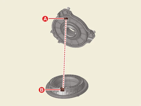
• Align the protrusion of the insulator (A) and groove of the bearing (B) when assembling.
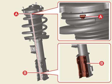
• When installing insulator assembly to the front strut assembly, align the protrusion (A) of the strut bearing and knuckle mounting parts (B).
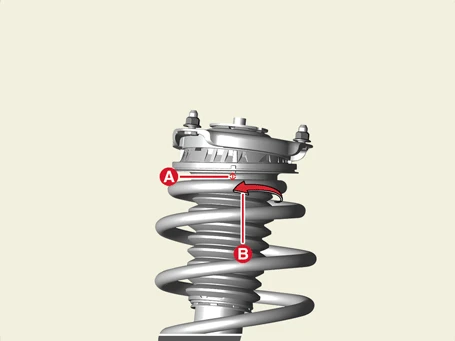
• When installing the coil spring, make sure that the gap (A) between the spring top start and 180° past point (B) and the spring upper pad is within the allowable value.
Allowable clearance (A) :3 mm (0.1181 in.)
2.Install the front strut assembly (A) to the spring compressor.
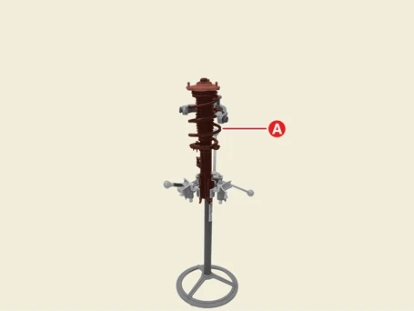
3.Compress the coil spring (A) slightly until it is tensioned using the spring compressor.
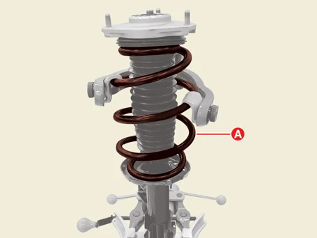

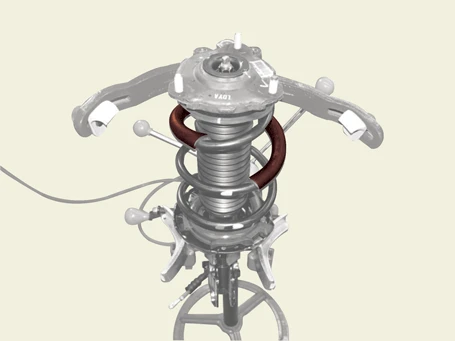
4.Install the self locking nut using SST (0K546 - F6100).
Tightening torque :107.9 - 117.7 N·m (11.0 - 12.0 kgf·m, 79.6 - 86.8 lb·ft)

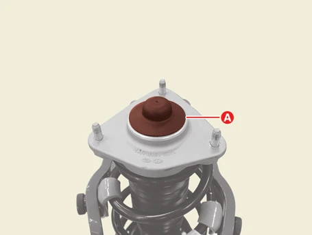
5.Install the insulator cap (A).
6.Install the front strut assembly.(Refer to Front Suspension System - "Front Strut Assembly")
