Component
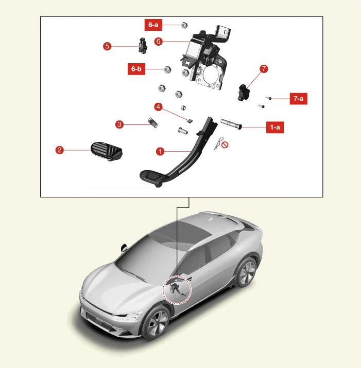
1. Brake Pedal Arm
1-a. 24.5 - 34.3 N·m (2.5 - 3.5 kgf·m, 18.1 - 25.3 lb·ft)
2. Brake Pedal Pad
3. Return Spring
4. Stopper
5. Stop Lamp Switch
6. Brake Pedal Member Assembly
6-a. 16.7 - 25.5 N·m (1.7 - 2.6 kgf·m, 12.3 - 18.8 lb·ft)
6-b. 12.7 - 17.7 N·m (1.3 - 1.8 kgf·m, 9.4 - 13.0 lb·ft)
7. Pedal Stroke Sensor
7-a. 2 - 3.9 N·m (0.2 - 0.4 kgf·m, 1.4 - 2.9 lb·ft)
Removal
1.Disconnect the battery negative ( - ) terminal and the service interlock connector.(Refer to Battery Control System - "Auxiliary 12 V Battery - 2WD")(Refer to Battery Control System - "Auxiliary 12 V Battery - 4WD")
2.Remove the knee air bag.(Refer to Restraint - "Knee Airbag (KAB)" )
3.Disconnect the stop lamp switch connector (A).
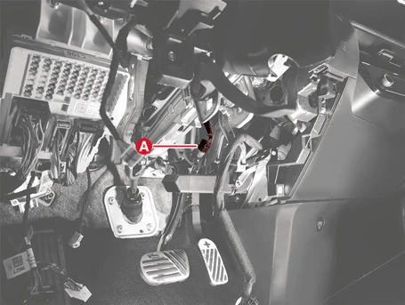
4.Disconnect the pedal stroke sensor connector (A).
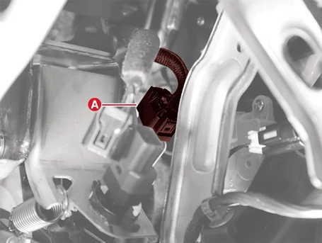
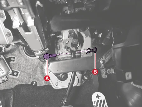
5.Remove the brake pedal arm mounting clevis pin (A) and split pin (B).

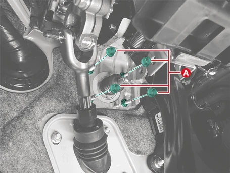
6.Remove the Integrated Electronic Brake (IEB) assembly nuts (A).
Tightening torque :12.7 - 17.7 N·m (1.3 - 1.8 kgf·m, 9.4 - 13.0 lb·ft)
7.Remove the front trunk.(Refer to Body - "Front Trunk")
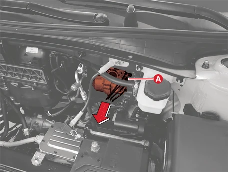
8.Move IEB (A) in the direction of the arrow and make a workspace.
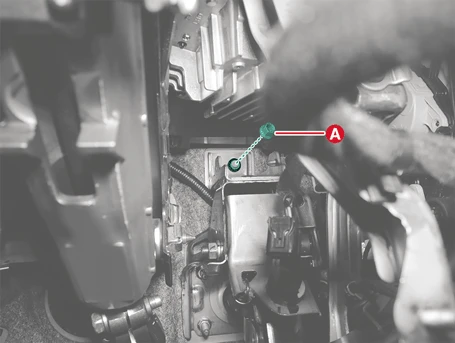
9.Remove the brake pedal assembly after removing the nut (A).
Tightening torque :16.7 - 25.5 N·m (1.7 - 2.6 kgf·m, 12.3 - 18.8 lb·ft)
Installation
1.Install in the reverse order of removal.

• Apply the grease when installing the brake pedal arm clevis pin (Grease type : GREASE PDLV-1)
• Be careful not to change the mounting position of the clevis pin and split pin.

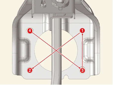
2.Check the brake pedal operating normally after installation.
3.After replacing the brake pedal assembly, make sure to set the Brake Pedal Travel Sensor (PTS) Calibration Procedure.(Refer to Brake System - "Pedal Travel Sensor (PTS) calibration")
4.Check the brake fluid leakage and pedal operating condition.
5.Fill the brake reservoir with brake fluid and perform the brake bleeding procedure.(Refer to Brake System - "Brake Bleeding Procedures")
Disassembly
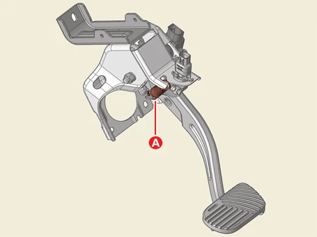
1.Remove the brake pedal return spring (A).
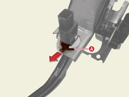
2.Pull the locking plate (A) in the direction of the arrow.
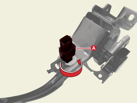
3.Remove the stop lamp switch (A) by turning counterclockwise.
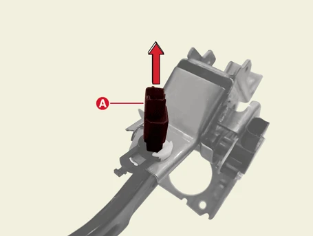
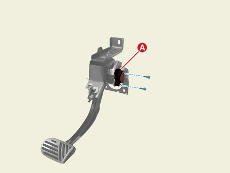
4.Remove the brake pedal stroke sensor (A) after removing the bolts.
Tightening torque :2.0 - 2.4 N·m (0.2 - 0.24 kgf·m, 1.4 - 1.7 lb·ft, 17.4 - 20.8 lb·in)

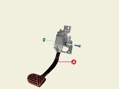
5.Disassemble the brake pedal arm (A) after removing the bolt and nut.
Tightening torque :24.5 - 34.3 N·m (2.5 - 3.5 kgf·m, 18.1 - 25.3 lb·ft)
Reassembly
1.Reassemble in the reverse order of disassembly.

2.Check the stop lamp switch clearance.(Refer to Stop Lamp Switch - "Inspection")
Brake Pedal Travel Sensor (PTS) Calibration Procedure
The calibration must be done while the vehicle is parked without stepping on the brake pedal and while there is no vibration on the vehicle.'Calibration' is performed in the following situations.– The brake pedal assembly is replaced.
– When the Integrated Electronic Brake (IEB) is replaced.
– DTC code C138004 or C137902 has been founded.

Zero setting procedures
The vehicle must not be braked or shaken when performing zero setting.1.Connect the KDS.
2.Turn ignition switch ON.
3.Select the 'Brake' and 'Pedal Travel Sensor (PTS) Calibration' on the KDS menu.
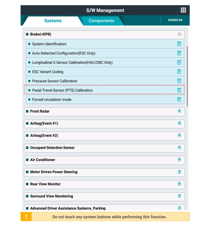
4.Follow the instructions to calibrate the PTS.
5.Turn off and on the vehicle and make sure the calibration is completed properly.