Removal

• When working on the high voltage system, the work should be performed by technicians who have completed the relevant training. A lack of understanding of the high voltage system can lead to serious accidents due to electric shock or short circuit.
• When working on the high voltage system or related components, be sure to observe and be aware of the "Safety Precautions, Cautions and Warnings". If not, it may cause serious accidents due to electric shock or short circuit.
• When working on high voltage system, make sure to check the Personal Protective Equipment (PPE) and high voltage shut-off procedure.
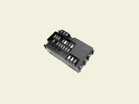
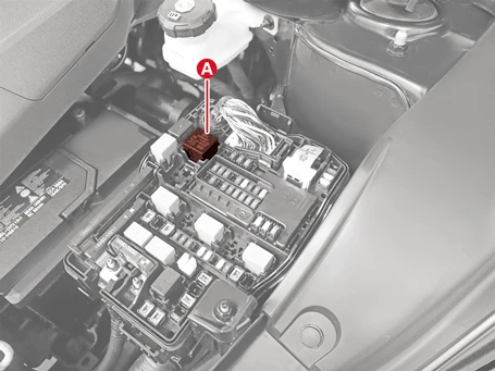
PE Room PCB Block
1.Disconnect the battery negative ( - ) terminal and the service interlock connector.(Refer to Battery Control System - "Auxiliary 12 V Battery - 2WD")(Refer to Battery Control System - "Auxiliary 12 V Battery - 4WD")
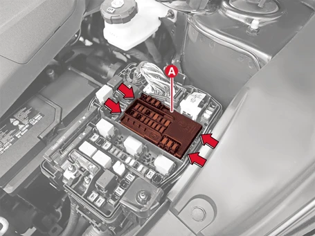
2.Remove the PE room PCB block (A) after pushing the hooks in the direction of the arrow.
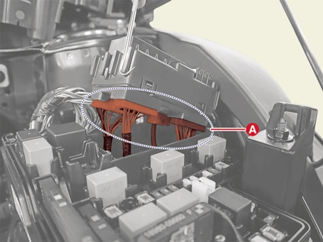
3.Disconnect the PE room PCB block connectors (A).
Installation

• When working on the high voltage system, the work should be performed by technicians who have completed the relevant training. A lack of understanding of the high voltage system can lead to serious accidents due to electric shock or short circuit.
• When working on the high voltage system or related components, be sure to observe and be aware of the "Safety Precautions, Cautions and Warnings". If not, it may cause serious accidents due to electric shock or short circuit.
• When working on high voltage system, make sure to check the Personal Protective Equipment (PPE) and high voltage shut-off procedure.
1.Install in the reverse order of removal.
Inspection
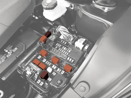
Power Relay (Type A)
Check for continuity between the terminals.1.After supplying power between terminal No. 85 and 86, check that there is continuity between terminal No. 30 and 87.
2.Disconnect power between terminal No. 85 and 86, check that there is no continuity between terminal No. 30 and 87.
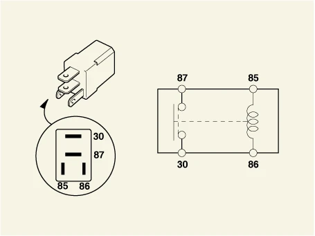
| Terminal | Operate | |
| Power ON | Power OFF | |
| 30 - 87 | Continuity | - |
Power Relay (Type B)
Check for continuity between the terminals.1.After supplying power between terminal No. 86 and 85, check that there is continuity between terminal No. 87 and 30.
2.Disconnect supplying power between terminal No. 86 and 85, check that there is no continuity between terminal No. 87 and 30.
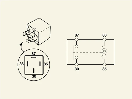
| Terminal | Operate | |
| Power ON | Power OFF | |
| 30 - 87 | Continuity | - |
Fuse
1.Check for separation of fuse holder and check that the holder is tightly holding the fuse.
2.Check that each fuse circuit has the exact fuse capacity.
3.Check the fuses for any damage.

Multi Fuse
1.Disconnect the battery negative ( - ) terminal and the service interlock connector.(Refer to Battery Control System - "Auxiliary 12 V Battery - 2WD")(Refer to Battery Control System - "Auxiliary 12 V Battery - 4WD")
2.Remove the multi fuse (A) by pulling the hook after removing the nut.
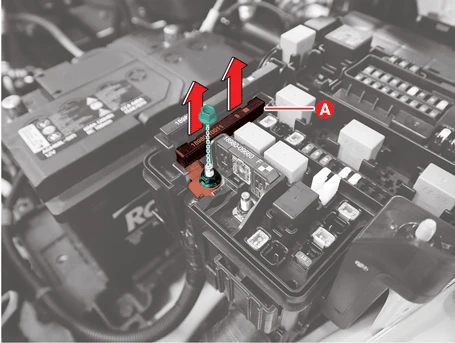
3.Remove the multi fuse (A) after pulling the hook.
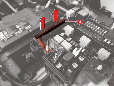
4.Remove the multi fuse (A) by pulling the hook after removing the nut.
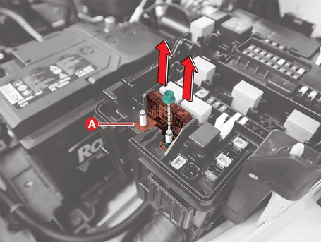
5.Check the multi fuses for any damage.
