Description
The Integrated Central Control Unit (ICU) is the next-generation model of the Integrated Gateway and Power Control Module (IGPM).
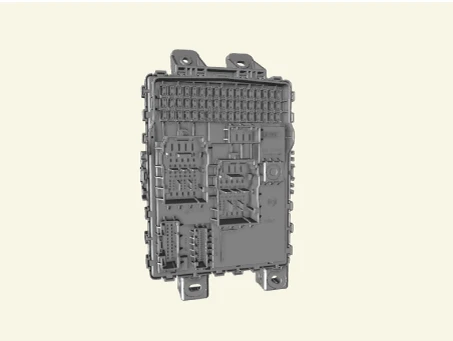
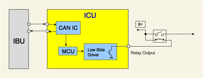
System Block Diagram
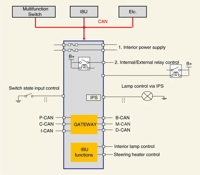
Function
| Item | Function | |
| Function | Switch input | Receives switch inputs and then sends the switch status to each module through CAN message. |
| Lamp control | Controls lamp with the IPS by receiving command from IBU via CAN message. | |
| Internal relay control | Controls internal relay by receiving command from IBU via CAN message. | |
| External relay control | Controls external relay by receiving command from IBU via CAN message. | |
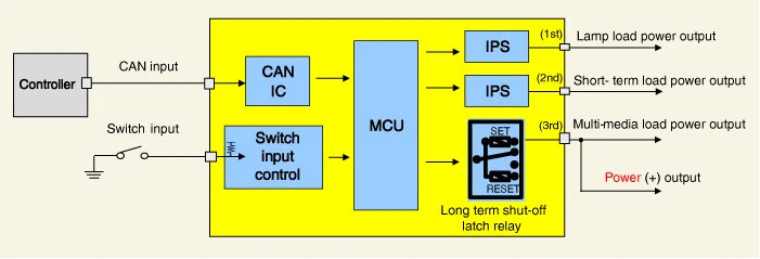
| Dark current shut off system | The system automatically shuts off the power to be provided with components for reducing useless dark current according to the vehicle operating conditions such as shipment and long-term parking. | |
| Troubleshooting | Diagnose status of loads controlled by IPS. | |
| Gateway | Transmits signals among the modules connected to the different networks in the vehicle. | |

▶ Self-Logic Function : Hazard lamp, Stop lamp, Tailgate room lamp, Steering heater, Door lock/unlock
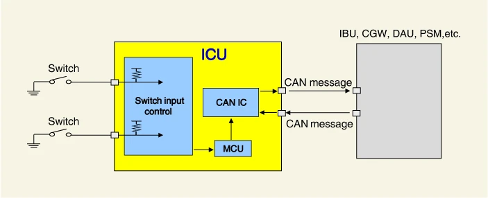
Switch Input
1.Operating Function▶ Hazard lamp switch, Seat belt switch, Tailgate switch, Door switch, etc.
2.Operating Description
(1)Determined switch operation status
(2)Switch status messages are sent to other modules (IBU, CGW, DAU, PSM, etc.) via CAN communication.
IPS Lamp control
1.Operating Description ▶ Headlamp low/high, Turn signal lamp, DRL lamp, Internal/External tail lamp, Stop lamp, etc.
2.Operating Description
(1)Lamp on/off operation via CAN message of IBU
(2) Detects current flowing through the lamp via IPS
(3)Lamp OFF when over-current detection (PCL control : Shut off current of lamp if reference current is exceeded)


Internal relay control
1.Operating Function▶ Burglar alarm horn, Tailgate, Power window, etc.
2.Operating Description
(1)Relay on/off operation via CAN message of IBU
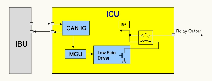
External relay control
1.Operating Function▶ Headlamp high solenoid, Rear Glass Defogger, etc.
2.Operating Description
(1)Relay on/off operation via CAN message of IBU
Dark current shut off system
1.Operating Description
(1)If the CAN and switch inputs are absent for a long time, the power output is turn off sequentially to prevent battery discharge.
(2)If a CAN or switch input is received while the dark current shut off system is operating, the system is disabled for normal operation.
Inspection
Fuse
1.Check for separation of fuse holder and check that the holder is tightly holding the fuse.
2.Check that each fuse circuit has the exact fuse capacity.
3.Check the fuses for any damage.

Removal

• When working on the high voltage system, the work should be performed by technicians who have completed the relevant training. A lack of understanding of the high voltage system can lead to serious accidents due to electric shock or short circuit.
• When working on the high voltage system or related components, be sure to observe and be aware of the "Safety Precautions, Cautions and Warnings". If not, it may cause serious accidents due to electric shock or short circuit.
• When working on high voltage system, make sure to check the Personal Protective Equipment (PPE) and high voltage shut-off procedure.
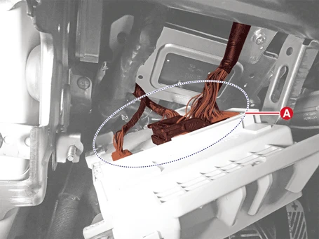
1.Remove the crash pad lower panel.(Refer to Body - "Crash Pad Panel")
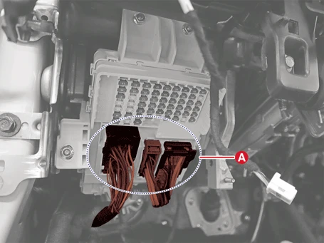
2.Disconnect the integrated central control unit (ICU) connectors (A).
3.Remove the ICU (A) after removing the nuts.
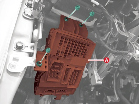
4.Disconnect the ICU connectors (A).
Installation

• When working on the high voltage system, the work should be performed by technicians who have completed the relevant training. A lack of understanding of the high voltage system can lead to serious accidents due to electric shock or short circuit.
• When working on the high voltage system or related components, be sure to observe and be aware of the "Safety Precautions, Cautions and Warnings". If not, it may cause serious accidents due to electric shock or short circuit.
• When working on high voltage system, make sure to check the Personal Protective Equipment (PPE) and high voltage shut-off procedure.
1.Install in the reverse order of removal.