Description
The heater unit is equipped with a mode actuator and a temperature control actuator.It is operated by a control switch and controls the position of the temperature control door to control the temperature of the discharge air.Removal

• When working on high voltage system, the work should be performed by technicians who have completed the relevant training. A lack of understanding of the high voltage system can lead to serious accidents due to electric shock or electric leakage.
• When working a high voltage system, the technician must be observed and aware of "High Voltage System General Safety Information and Caution". If not, it may cause serious accidents such as electric shock or short circuit.
• When working on high voltage system, make sure to check the Personal Protective Equipment (PPE) and high voltage shut-off procedures.
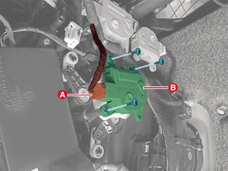
Driver's side Temperature Control Actuator
1.Disconnect the battery negative ( - ) terminal and the service interlock connector.(Refer to Battery Control System - "Auxiliary 12 V Battery - 2WD")(Refer to Battery Control System - "Auxiliary 12 V Battery - 4WD")
2.Remove the Knee Airbag (KAB).(Refer to Restraint - "Knee Airbag (KAB)")
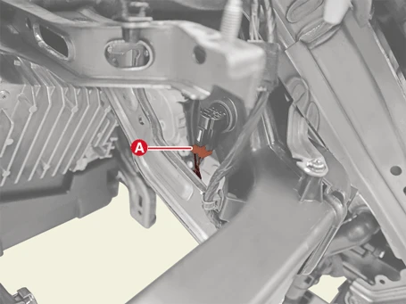
3.Disconnect the duct sensor connector (A).
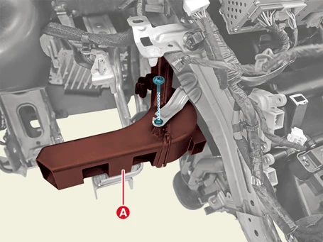
4.Remove the driver's side shower duct (A) after removing the screw.
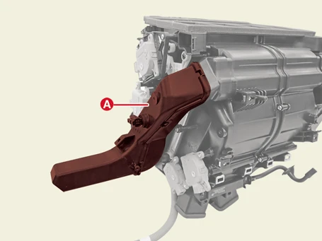
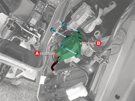
5.Disconnect the connector (A) and remove the driver's temperature control actuator (B) after removing the screws.
Passenger's side Temperature Control Actuator
1.Disconnect the battery negative ( - ) terminal and the service interlock connector.(Refer to Battery Control System - "Auxiliary 12 V Battery - 2WD")(Refer to Battery Control System - "Auxiliary 12 V Battery - 4WD")
2.Remove the glove box housing.(Refer to Body- "Glove Box")
3.Disconnect the connector (A) and remove the passenger temperature control actuator (B) after removing the screws.
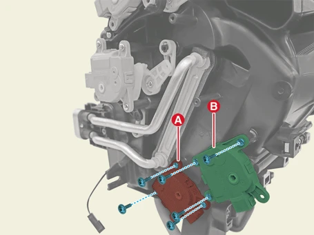
Rear Temperature Control Actuator
1.Disconnect the battery negative ( - ) terminal and the service interlock connector.(Refer to Battery Control System - "Auxiliary 12 V Battery - 2WD")(Refer to Battery Control System - "Auxiliary 12 V Battery - 4WD")
2.Remove the cowl cross bar assembly.(Refer to Body - "Cowl Cross bar Assembly")
3.Remove the rear cooling actuator (A) and the rear heating actuator (B) after removing the screws.
Installation

• When working on high voltage system, the work should be performed by technicians who have completed the relevant training. A lack of understanding of the high voltage system can lead to serious accidents due to electric shock or electric leakage.
• When working a high voltage system, the technician must be observed and aware of "High Voltage System General Safety Information and Caution". If not, it may cause serious accidents such as electric shock or short circuit.
• When working on high voltage system, make sure to check the Personal Protective Equipment (PPE) and high voltage shut-off procedures.
1.Install in reverse order of removal.
Inspection
1.Turn IG OFF.
2.Disconnect the temperature control actuator connector.
3.Connect the power ( + ) terminal to the 3 terminal of the actuator connector and the ( - ) terminal to the 4 terminal and check whether the actuator is running. When connected in the opposite direction, check if it operates in reverse.
[Driver's seat]
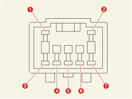
1. -
2. -
3. Cooling
4. Heating
5. Sensor Power (+5 V)
6. Feedback Signal
7. Sensor Ground
[Passenger's seat]
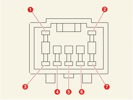
1. -
2. -
3. Cooling
4. Heating
5. Sensor Power (+5 V)
6. Feedback Signal
7. Sensor Ground
[Rear cooling]
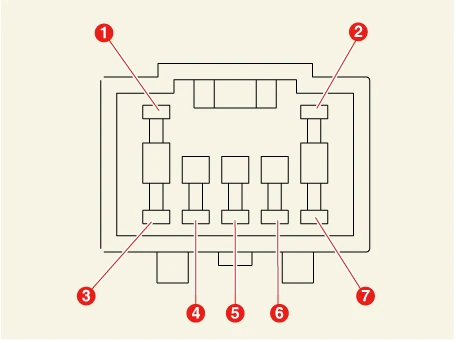
1. -
2. -
3. Cooling Open
4. Cooling Closed
5. Sensor Ground
6. Feedback Signal
7. Sensor Power (+5 V)
[Rear heating]
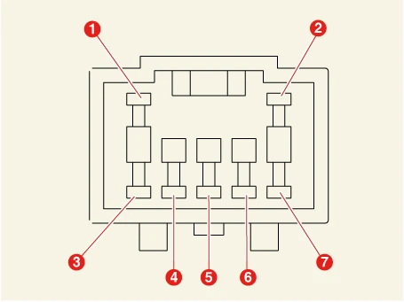
1. -
2. -
3. Heating Open
4. Heating Closed
5. Sensor Ground
6. Feedback Signal
7. Sensor Power (+5 V)
4.Connect the temperature control actuator connector.
5.Turn IG ON.
6.Measure the terminal voltage. [Driver's seat] : between 5 and 6.[Passenger's seat], [Rear cooling], [Rear heating] : between 7 and 6.
| Door position | Voltage (V) | Error detection |
| 0 ° | 0.5 ± 0.15 |
Low voltage : less than 0.1 V High voltage : more than 4.9 V |
| 80 ° | 4.5 ± 0.15 |
* Feedback the current position of the actuator to the control.
7.If the measured voltage does not match with the specifications, replace it with a new temperature control actuator.