Specification
| Item | Specification |
| Operating voltage (V) | 9 - 16 |
| Operating temperature [°C (°F)] | -35 to 75 (-31 to 167) |
| Insulated resistance (MΩ) | 10 (at 2 kV) |
Component
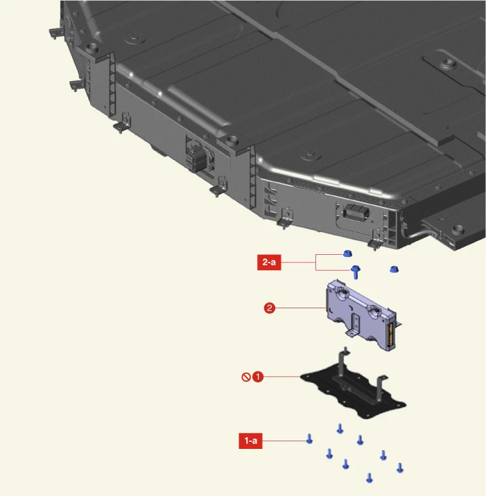
1. Service Cover
1-a. 1st : 8.8 N·m (0.9 kgf·m, 6.5 lb·ft)
1-a. 2nd : 10.8 N·m (1.1 kgf·m, 8.0 lb·ft)
2. Battery Management Unit (BMU)
2-a. 1st : 8.8 N·m (0.9 kgf·m, 6.5 lb·ft)
2-a. 2nd : 10.8 N·m (1.1 kgf·m, 8.0 lb·ft)
On Vehicle Inspection

• When working on high voltage system, the work should be performed by technicians who have completed the relevant training. A lack of understanding of the high voltage system can lead to serious accidents due to electric shock or electric leakage.
• When working on high voltage system or related components, make sure that you are familiar and comply with the "Safety Precautions, Cautions and Warnings." If you do not comply with the instructions, serious accidents due to electric shock or leakage may occur.
• When working on high voltage system, make sure to check the Personal Protective Equipment (PPE) and high voltage shut-off procedures.

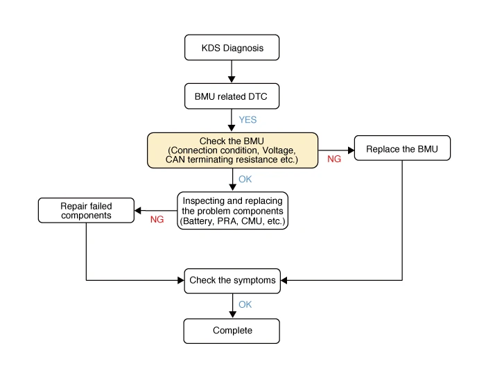
1.Diagnose the Battery Management Unit (BMU) with the KDS. (Refer to DTC manual)

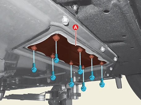
2.Remove the BMU service cover (A) after removing the bolts.
Tightening torque1st : 8.8 N·m (0.9 kgf·m, 6.5 lb·ft)2nd : 10.8 N·m (1.1 kgf·m, 8.0 lb·ft)
3.When the BMU failures, inspect or replace it if necessary.Connector connection condition
(1)Check the BMU connectors (A) connection condition.
(1)Measure the G-CAN line voltage with IG ON.
Inspection area : Ground the D19 of CAN LOW and vehicle body, and ground the D20 of CAN HIGH and ground.Specification value (V) : 1.5 - 3.5
(2)Measure the G-CAN line terminating resisters.
Inspection area : D19 and D20Specification value (Ω) : 120
4.If the BMU is normal, inspect the components related with fault code (DTC).

Removal

• When working on high voltage system, the work should be performed by technicians who have completed the relevant training. A lack of understanding of the high voltage system can lead to serious accidents due to electric shock or electric leakage.
• When working on high voltage system or related components, make sure that you are familiar and comply with the "Safety Precautions, Cautions and Warnings." If you do not comply with the instructions, serious accidents due to electric shock or leakage may occur.
• When working on high voltage system, make sure to check the Personal Protective Equipment (PPE) and high voltage shut-off procedures.
1.Shut off the high voltage circuit.(Refer to Battery Control System (Long Range) - "High Voltage Shut-off Procedures")
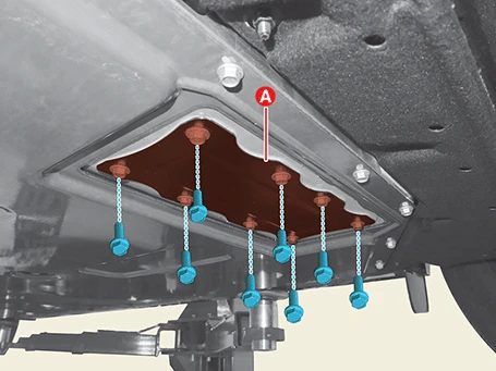
2.Remove the Battery Management Unit (BMU) service cover (A) after removing the bolts.
Tightening torque1st : 8.8 N·m (0.9 kgf·m, 6.5 lb·ft)2nd : 10.8 N·m (1.1 kgf·m, 8.0 lb·ft)
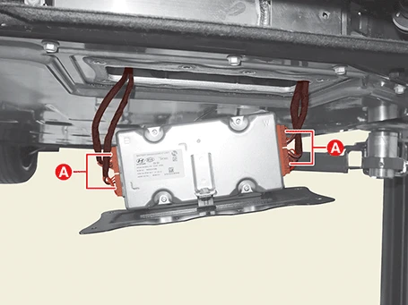
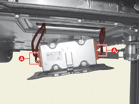
3.Disconnect the BMU connectors (A).
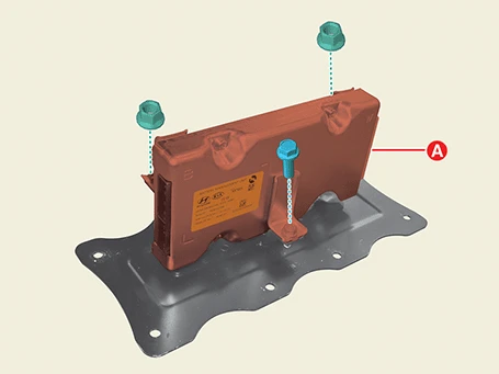
4.Remove the BMU (A) from the service cover after removing the bolt and nuts.
Tightening torque1st : 8.8 N·m (0.9 kgf·m, 6.5 lb·ft)2nd : 10.8 N·m (1.1 kgf·m, 8.0 lb·ft)
Installation

• When working on high voltage system, the work should be performed by technicians who have completed the relevant training. A lack of understanding of the high voltage system can lead to serious accidents due to electric shock or electric leakage.
• When working on high voltage system or related components, make sure that you are familiar and comply with the "Safety Precautions, Cautions and Warnings." If you do not comply with the instructions, serious accidents due to electric shock or leakage may occur.
• When working on high voltage system, make sure to check the Personal Protective Equipment (PPE) and high voltage shut-off procedures.
1.Install in the reverse order of removal.

• Install the Battery Management Unit (BMU) to the specified torque.
• If the BMU is dropped, it may cause internal damage. (Do not reuse)
• Install the service cover after completely removing existing tape on the battery side to prevent the air leakage.
• The service cover should be replaced with a new one. (Do not reuse)
2.Perform the air tightness inspection with the KDS.(Refer to High Voltage Battery System - "Air Tightness Inspection")
3.Perform the SOC calibration with the KDS.(S/W management → Battery Management System (BMS) → SOC Calibration)
4.Perform the SOH reset with the KDS.(S/W management → Battery Management System (BMS) → SOH Reset)
