Components and Components Location
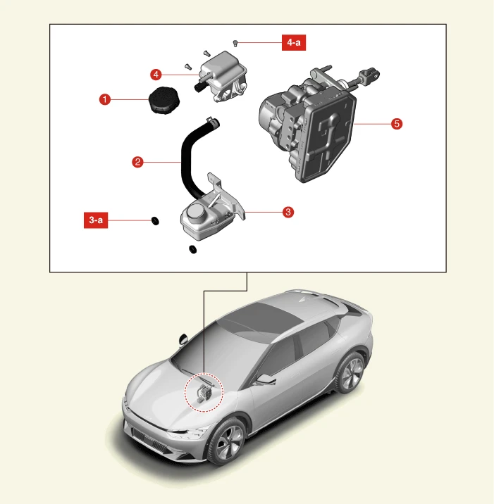

1. Reservoir Cap
2. Remote Reservoir Tank Hose
3. Remote Reservoir Tank
3-a. 6.9 - 10.8 N·m (0.7 - 1.1 kgf·m, 5.1 - 8.0 lb·ft)
4. Reservoir Tank
4-a. 1.0 - 1.5 N·m (0.10 - 0.15 kgf·m, 0.7 - 1.1 lb·ft, 8.7 - 13 lb·in)
5. Integrated Electronic Brake (IEB)
Removal

• When working on high voltage system, the work should be carried by technicians who have completed the relevant training. It is because that lack of knowledge of the high voltage system can lead to serious accidents due to electric shock or electric leakage.
• When working on high voltage system or related system, make sure that you are familiar and comply with the "Safety Precautions, Cautions and Warnings." If you do not comply with the instructions, serious accidents due to electric shock or leakage may occur.
• When working on high voltage system, make sure to check the Personal Protective Equipment (PPE) and high voltage shut-off procedures.
1.Disconnect the battery negative ( - ) terminal and the service interlock connector.(Refer to Battery Control System - "Auxiliary 12 V Battery - 2WD")(Refer to Battery Control System - "Auxiliary 12 V Battery - 4WD")
2.Remove the front trunk.(Refer to Body - "Front Trunk")
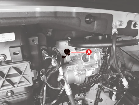
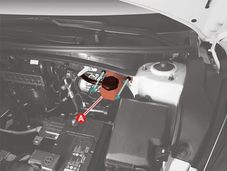
3.Disconnect the brake fluid level sensor (A).
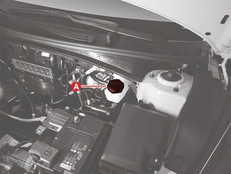
4.Remove the brake fluid from the reservoir tank by using a suitable tool after opening the reservoir cap (A).


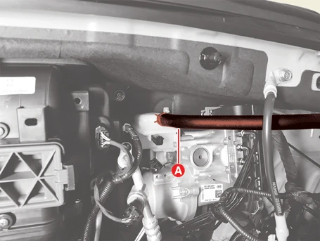
5.Separate the remote reservoir tank hose (A) after releasing the clamp.
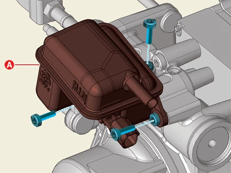
6.Remove the reservoir tank assembly (A) after removing the nuts.
Tightening torque :6.9 - 10.8 N·m (0.7 - 1.1 kgf·m, 5.1 - 8.0 lb·ft)
7.Remove the reservoir tank (A) after removing the screws.
Tightening torque :1.0 - 1.5 N·m (0.10 - 0.15 kgf·m, 0.7 - 1.1 lb·ft, 8.7 - 13 lb·in)
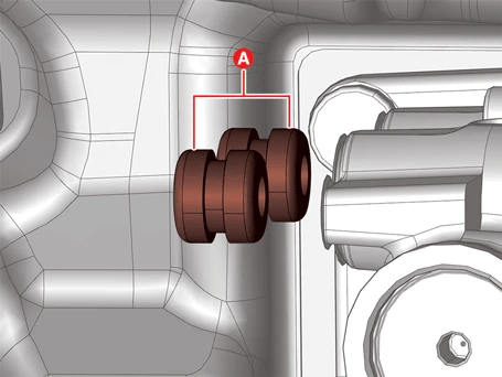
8.Remove the grommets (A).

Installation
1.Install in the reverse order of removal.

2.Fully fill the reservoir tank with brake fluid and perform the air bleed procedure.(Refer to Brake System - "Brake Bleeding Procedures")
3.Check the brake fluid leakage and pedal operating condition.