Battery Diagnosis for The Partial Module Repair

• If it is necessary to partially repair the high voltage battery, check whether it is possible to partially repair the high voltage battery according to the conditions below.
• For accurate diagnosis, conduct the diagnosis under the conditions "Keep SOH 20% or higher, 25°C (77°F) or higher for 5 seconds" regardless of mileage and SOH.
• Do not partially repair the battery module if the conditions below are not met. Problems can occur due to differences in performance between new and existing batteries.
If the vehicle mileage < 30,000 km (18,000 mile)
If the vehicle mileage > 30,000 km (18,000 mile)
Inspection

• State of Charge (SOC) : Percentage of the usable battery energy vs. a fully charged battery
• SOC calibration should be performed with the KDS to check the correct SOC value after replacing the Battery System Assembly (BSA) or Sub Battery Pack Assembly (Sub-BPA).
• When driving after replacing the Battery System Assembly (BSA) or Battery Module Assembly (BMA), it is calibrated to a normal SOC within 30 minutes.
• Refer to the KDS screen for operating conditions and details.
1.Check the SOC in service data with the KDS.(Data Analysis → Battery Management System (BMS) → State of Charge of Battery)
Inspection


• State of health (SOH) is the current state condition of a battery (or a cell, or a battery pack), compared to its ideal conditions.
• Typically, a battery's SOH will be 100% at the time of manufacture and will decrease over time and use.
• Refer to the KDS screen for operating conditions and details.
1.Check the SOH with the KDS.(Data Analysis → Battery Management System (BMS) → State of Health of Battery)
New parts : 100%Partial repair standard : 90% or above
Inspection

• When working on high voltage system, the work should be performed by technicians who have completed the relevant training. A lack of understanding of the high voltage system can lead to serious accidents due to electric shock or electric leakage.
• When working on high voltage system or related components, make sure that you are familiar and comply with the "Safety Precautions, Cautions and Warnings." If you do not comply with the instructions, serious accidents due to electric shock or leakage may occur.
• When working on high voltage system, make sure to check the Personal Protective Equipment (PPE) and high voltage shut-off procedures.
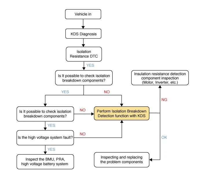
1.Check the Diagnosis Trouble Code (DTC) with the KDS.

• Insulation resistance values can also be checked with the KDS sensor data separately from the inspection procedure below.(Data Analysis → Battery Management System (BMS) → Isolation Resistance)
Specified value (kΩ) : 300 or above
• Refer to the KDS screen for operating conditions and details.
2.When the DTC related to insulation resistance occurs, inspect the problem components by using the fault data. (Refer to DTC guide manual)

3.If it is impossible to check for faulty components, perform the isolation breakdown detection function with the KDS.(Data Analysis → Battery Management System (BMS) → Isolation Breakdown Detection Function)


4.Check the insulation resistance of the problematic parts using a mega ohm tester and replace it if necessary.
Specified value (MΩ) : 2 or above [20°C (68°F)]

Inspection

• If battery module replacement is necessary, check whether it is possible to partial repair.(Refer to Battery System Assembly (BSA) Inspection - "Battery Diagnosis for The Partial Module Repair")
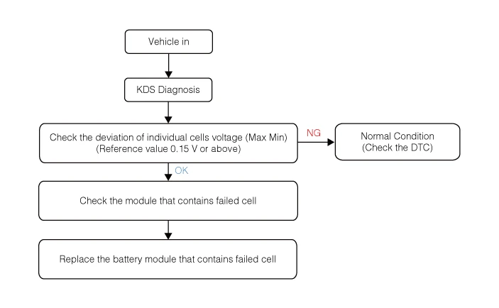
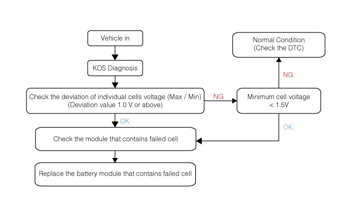
• Refer to the below flow chart for battery cell voltage inspection.
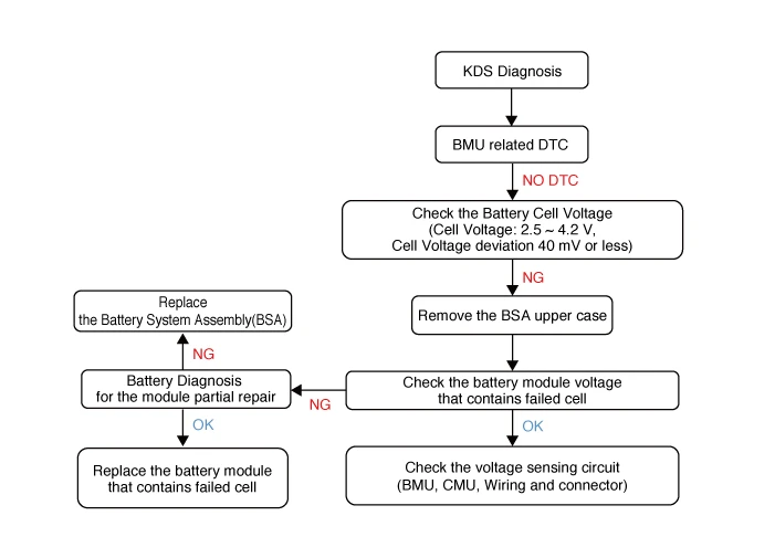
1.Check the battery cell voltage with the KDS.
Normal cell voltage (V) : 2.5 - 4.2 VVoltage deviation between cells (mV) : 40 or below

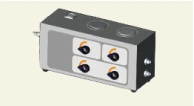
2.Remove the Battery System Assembly (BSA) upper case.(Refer to High Voltage Battery System - "Case")
3.Measures the voltage of the battery module that contains the faulty cell.

4.Replace the Battery System Assembly (BSA) or Battery Module Assembly (BMA) according to condition for partial repair.(Refer to High Voltage Battery System - "Battery System Assembly (BSA)")(Refer to High Voltage Battery System - "Battery Module Assembly (BMA)")
Special Service Tool
| Tool Name | Illustration | Description |
|
Coolant refiller & suction tool 0K253 - J2300 |
|
Used for filling and draining coolant to the High Voltage Battery System Assembly (BSA) |
|
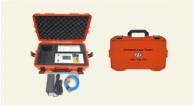
Air tightness test equipment GIT ULT - M100 G7XKDNN001 By GIT |
|
Used for inspecting the air tightness of the Battery System Assembly (BSA) and PE system |
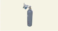
| Helium gas and pressure regulator |
|
Used for detecting micro-leakage (※ Helium gas detectors purchase commercial products) |
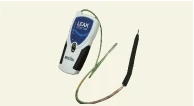
| Helium gas detector |
|
He, H2, Ar, CO2 Leak Detector 1) Maker : RESTEK / USA 2) Model number : No. 28500 |
air tightness Inspection for High Voltage Battery System and Coolant Line

• When working on high voltage system, the work should be performed by technicians who have completed the relevant training. A lack of understanding of the high voltage system can lead to serious accidents due to electric shock or electric leakage.
• When working on high voltage system or related components, make sure that you are familiar and comply with the "Safety Precautions, Cautions and Warnings." If you do not comply with the instructions, serious accidents due to electric shock or leakage may occur.
• When working on high voltage system, make sure to check the Personal Protective Equipment (PPE) and high voltage shut-off procedures.

• After working on the Battery System Assembly (BSA) or Battery Module Assembly (BMA), perform the air tightness inspection by using the EV Battery Pack Air leak Tester.
• Drain the coolant in Battery System Assembly (BSA) before checking it.

1.Remove the battery system assembly (BSA).(Refer to High Voltage Battery System - "Battery System Assembly (BSA)")
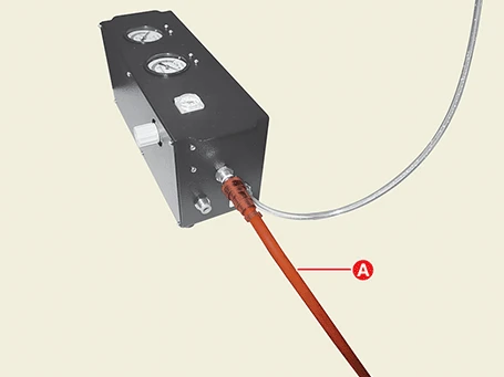
2.Install the coolant adapter (A, B).
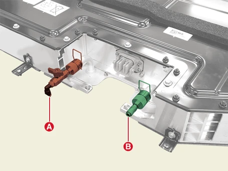
3.Connect the hose (B) to inlet adapter (A).
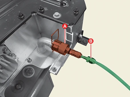
4.Connect the opposite side of inlet hose (A) to air pressure line of SST (0K253 - J2300).
5.Install the hose (B) to the outlet adapter (A) and put the opposite of hose to a bucket.

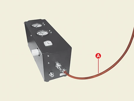
6.Connect the air hose (A) to SST (0K253 - J2300).
7.Set the regulator pressure gauge (B) to 0.2 MPa (2.1 bar) by using the regulator valve (A).
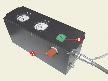

8.Turn the pressure valve (A) of SST (0K253 - J2300) in the direction of arrow.
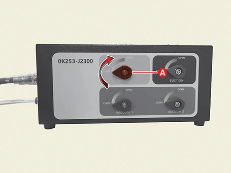
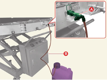
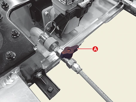
9.Drain the coolant by opening the outlet adapter valve (A) slowly.

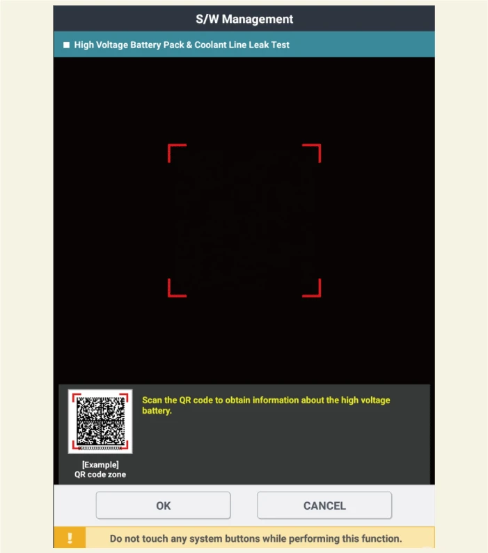
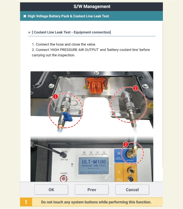
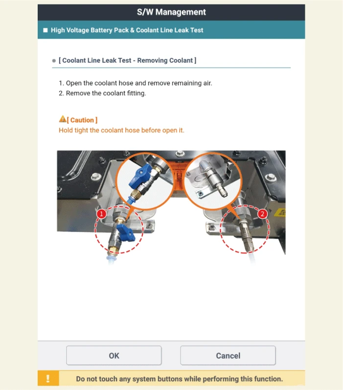
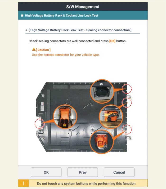
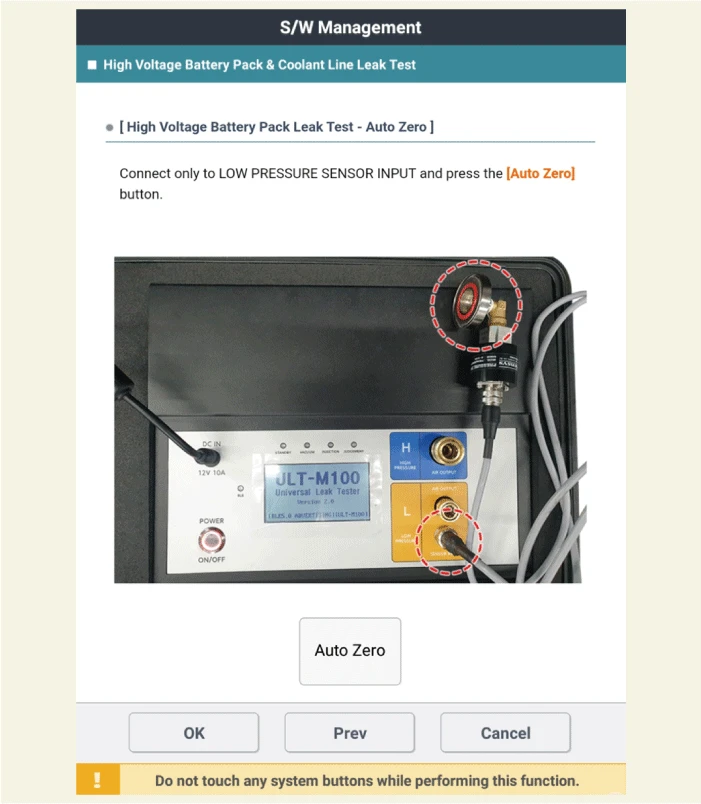
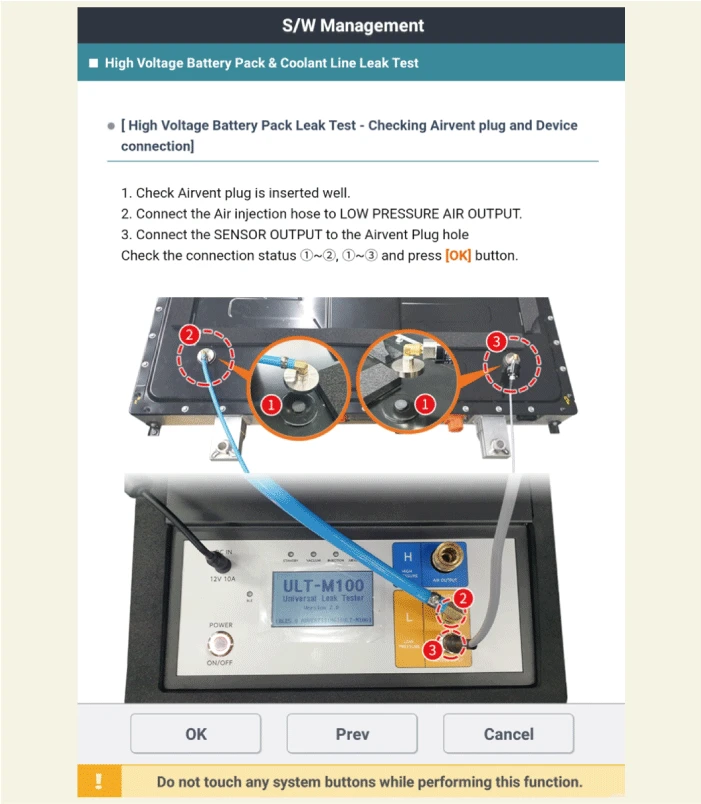
10.When the coolant drain is complete, remove the air bleeding tool and then inspect the high voltage battery system & coolant line air tightness with the KDS. (S/W management → Battery Management System (BMS) → High Voltage Battery Pack & Coolant Line Leak Test)

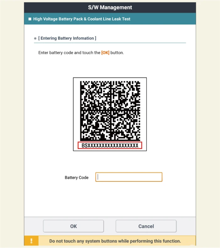
11.Scan the QR code on the high voltage battery upper case.

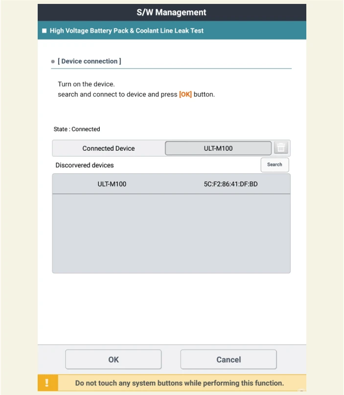
12.Connect the EV battery pack airtight check tester equipment and KDS.
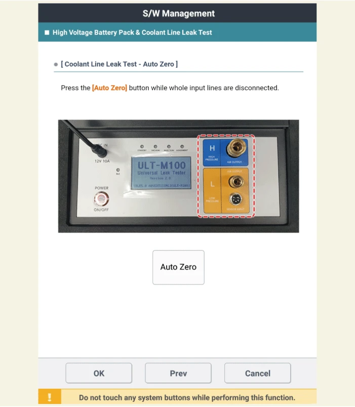
13.Perform the air tightness inspection according to KDS screen description.
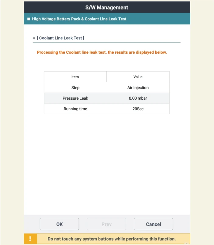
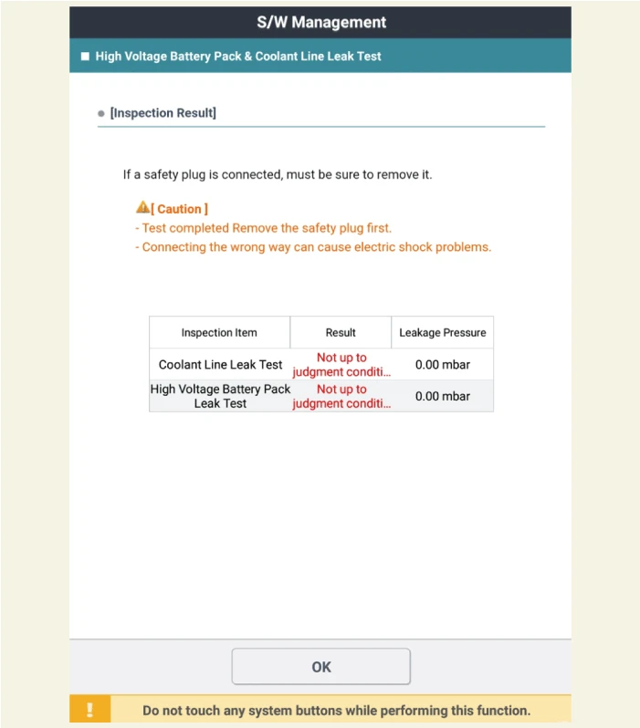
14.Check the results after inspecting the BSA air tightness.

• If the results of the air tightness inspection fail, check the leakage area by referring to the procedures below.
• Helium gas, pressure regulator, and leak detector are required to check for leak area.
• Helium, regulators, and helium gas detectors purchase commercial products to detect micro-leakage (0.1 - 0.3 mbar) and secure complete confidentiality of the pack.
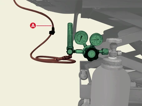
(1)Attach the adapter (A) to the pressure regulator.
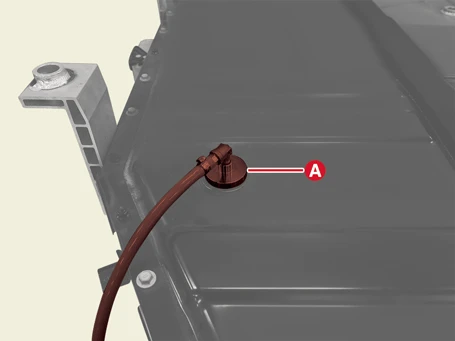

(2)Install the adapter hose (A) to the helium gas valve.
(3)Attach the pressure sensor module (A) to the pressure regulator.
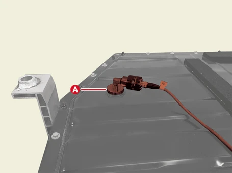

(4)Install the pressure sensor module (A) to the SENSOR INPUT of air tightness equipment.
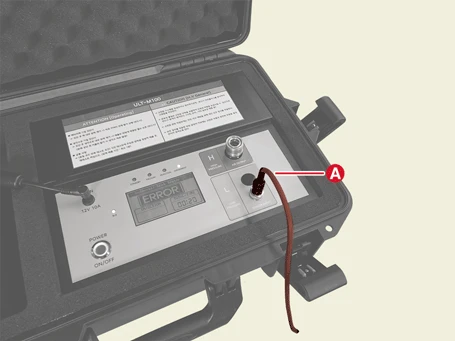
(5)Inject the helium gas.

(6)Check the leakage area in the Battery System Assembly (BSA) by using the leak tester.

• Check the welded part of the lower case and the connection part of the battery connector.
• In many cases where air tightness cannot be maintained near the gasket, therefore, around the gasket is mainly checked with a detector.