Components and Components Location
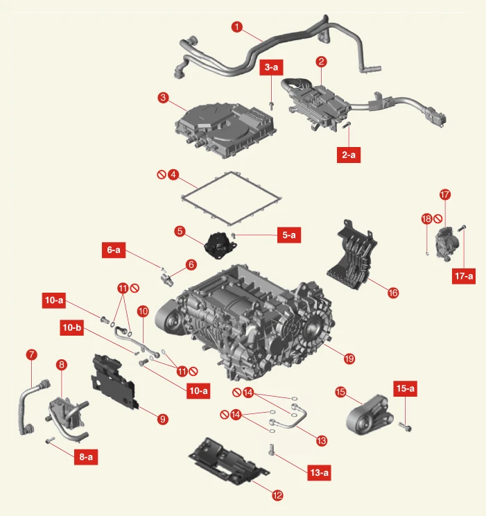
1. Water Hose Assembly
2. Rear High Voltage Junction Box
2-a. 9.8 - 11.8 N·m (1.0 - 1.2 kgf·m, 7.2 - 8.7 lb·ft)
3. Multi Inverter Assembly
3-a. 4.0 - 5.8 N·m (0.4 - 0.6 kgf·m, 2.9 - 4.3 lb·ft, 34.7 - 52.0 lb·in)
4. Multi Inverter Assembly Gasket
5. SBW(Shift By Wire) Actuator
5-a. 20.6 - 27.5 N·m (2.1 - 2.8 kgf·m, 15.2 - 20.3 lb·ft)
6. Motor Position and Temperature Sensor
6-a. 9.8 - 11.8 N·m (1.0 - 1.2 kgf·m, 7.2 - 8.7 lb·ft)
7. Motor and Reduction Gear Oil Cooler Cooling Hose
8. Motor and Reduction Gear Oil Cooler
8-a. 6.9 - 9.8 N·m (0.7 - 1.0 kgf·m, 5.1 - 7.2 lb·ft)
9. Rear Motor Rear Cover
10. Tube Pipe B
10-a. 41.2 - 47.1 N·m (4.2 - 4.8 kgf·m, 30.4 - 34.7 lb·ft)
11. Tube Pipe B Gasket
12. Rear Motor Lower Cover
13. Tube Pipe A
13-a. 41.2 - 47.1 N·m (4.2 - 4.8 kgf·m, 30.4 - 34.7 lb·ft)
14. Tube Pipe A Gasket
15. RH Motor Mounting Bracket
15-a. 63.7 - 83.4 N·m (6.5 - 8.5 kgf·m, 47 - 61.5 lb·ft)
16. Rear Motor Front Cover
17. Electronic Oil Pump (EOP)
17-a. 19.6 - 26.5 N·m (2.0 - 2.7 kgf·m, 14.5 - 19.5 lb·ft)
18. O-ring
19. Rear Motor and Reduction Gear Assembly
Installation
1.Install in the reverse order of removal.

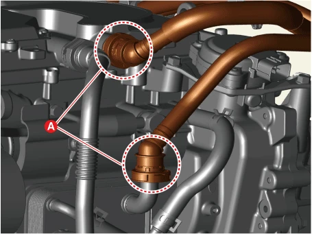
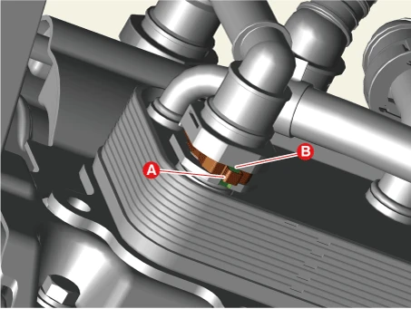
2.Fill the coolant.(Refer to Electric Vehicle Cooling System - "Coolant")

3.Refill the rear motor and reduction gear oil.(Refer to Rear Motor and Reduction Gear System - "Rear Motor and Reduction Gear Oil")
4.After installing the rear motor and reduction gear assembly, perform the leakage test. (Refer to Battery Control System - "Air Tightness")
5.Perform the "Motor Control Unit-Rear" and "Initialization of Automatic Resolver Offset Calibration" using the KDS.(Refer to Motor and Reduction Gear System - Motor Position & Temperature Sensor)

Inspection
[Phase Resistance]
1.Remove the rear high voltage junction box.(Refer to Battery Control System - "Rear High Voltage Junction Box")
2.Remove the multi inverter assembly.(Refer to Battery Control System - "Multi Inverter Assembly")
3.Check the resistance of each line (U, V, W) using a multi-ohm meter.
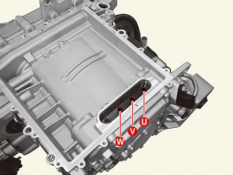
| Item | Inspection area | Specifications | Remark |
|
Phase resistance (Line - Line) |
U - V | 57.48 - 63.52 mΩ | Reference temperature : 20 - 20.08°C (68 - 68.1°F ) |
| V - W | |||
| W - U |
[Insulation Resistance]
1.Remove the rear high voltage junction box.(Refer to Battery Control System - "Rear High Voltage Junction Box")
2.Remove the multi inverter assembly.(Refer to Battery Control System - "Multi Inverter Assembly")
3.Using an insulation resistance tester and check insulation resistance.
(1)Connect the ( - ) terminal of the insulation resistance tester to the housing, ( + ) terminal, and 3-phase (U, V, W).
(2)Supply the DC 1,000 V voltage through insulation resistance tester and then wait about 1 minute to measure the stable resistance value.
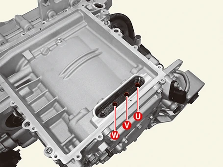
| Item | Inspection area | Specifications | Remark |
| Insulation resistance | Housing - U | 100 MΩ or more | DC 1,000 V, 1 minute |
| Housing - V | |||
| Housing - W |
[Dielectric Strength]
1.Remove the rear high voltage junction box.(Refer to Battery Control System - "Rear High Voltage Junction Box")
2.Remove the multi inverter assembly.(Refer to Battery Control System - "Multi Inverter Assembly")
3.Using a withstanding voltage tester check leakage current.
(1)Connect the ( - ) terminal of the withstand voltage tester to the housing and the ( + ) terminal to the 3-phase (U, V, W).
(2)Check the measured value by applying AC 2,200 V for one minute.
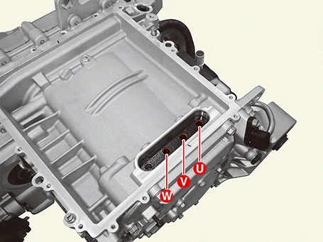
| Item | Inspection area | Specifications | Remark |
| Dielectric strength | Housing - U | 18 mA or less | AC 2,200 V, 1minute |
| Housing - V | |||
| Housing - W |