Specification
| Accelerator Pedal Position | Output Voltage (V) | |
| APS 1 | APS 2 | |
| Idle Stroke | 0.7 - 0.8 | 0.33 - 0.43 |
| Full Stroke | 3.98 - 4.22 | 1.93 - 2.17 |
On Vehicle Inspection
1.Diagnostic equipment (KDS) can be used to diagnose fault parts quickly. (Refer to "DTC Diagnostic Guide")
(1)Self diagnosis : Inspection and display failed code (DTC)
(2)Sensor data : Checks the system input/output values
(3)Forced operation : Checking the system operation condition
(4)Additional function : Controlling other features including system option setting and zero point adjustment
Component Inspection
1.Checks the output voltage of the sensor 1 and sensor 2 according to accelator pedal state by using a KDS.
| Accelerator Pedal Position | Output Voltage (V) | |
| APS 1 | APS 2 | |
| Idle Stroke | 0.7 - 0.8 | 0.33 - 0.43 |
| Full Stroke | 3.98 - 4.22 | 1.93 - 2.17 |
Removal
1.Disconnect the battery negative ( - ) terminal and the service interlock connector.(Refer to Battery Control System - "Auxiliary 12 V Battery - 2WD")(Refer to Battery Control System - "Auxiliary 12 V Battery - 4WD")
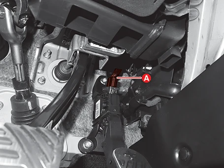
2.Disconnect the connector (A).

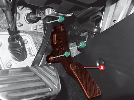
3.Remove the accelerator pedal module (A) after removing the nuts.
Tightening torque :12.7 - 15.7 N·m (1.3 - 1.6 kgf·m, 9.4 - 11.6 lb·ft)

Installation
1.Install in the reverse order of removal.

• Install the accelerator pedal module to the specified torque values.
• If the accelerator pedal module is dropped, it may cause internal damage. Do not use it.