Components and Components Location
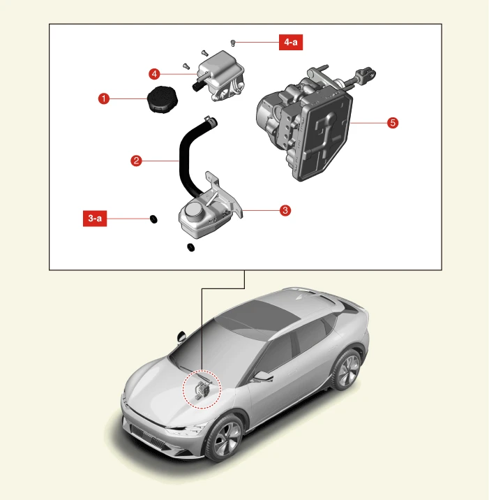

1. Reservoir Cap
2. Reservoir Hose
3. Remote Reservoir Tank
3-a. 6.9 - 10.8 N·m (0.7 - 1.1 kgf·m, 5.1 - 8.0 lb·ft)
4. Reservoir Tank
4-a. 1.0 - 1.5 N·m (0.10 - 0.15 kgf·m, 0.7 - 1.1 lb·ft, 8.7 - 13 lb·in)
5. Integrated Electronic Brake (IEB)
Removal

• When working on high voltage system, the work should be carried by technicians who have completed the relevant training. It is because that lack of knowledge of the high voltage system can lead to serious accidents due to electric shock or electric leakage.
• When working on high voltage system or related system, make sure that you are familiar and comply with the "Safety Precautions, Cautions and Warnings." If you do not comply with the instructions, serious accidents due to electric shock or leakage may occur.
• When working on high voltage system, make sure to check the Personal Protective Equipment (PPE) and high voltage shut-off procedures.

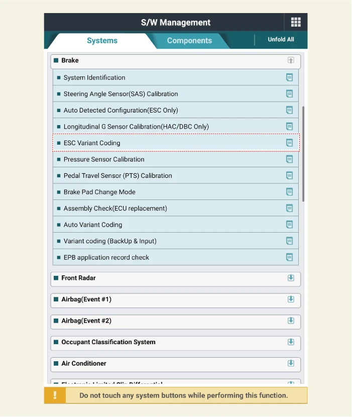
• Select 'Variant coding (Backup and Write)' on the S/W management menu and follow the on-screen instructions.
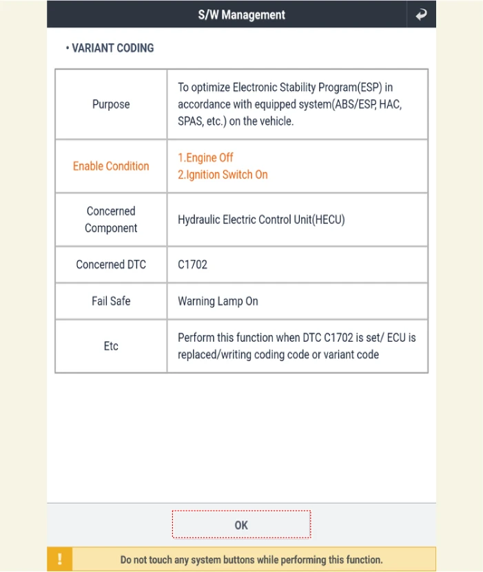
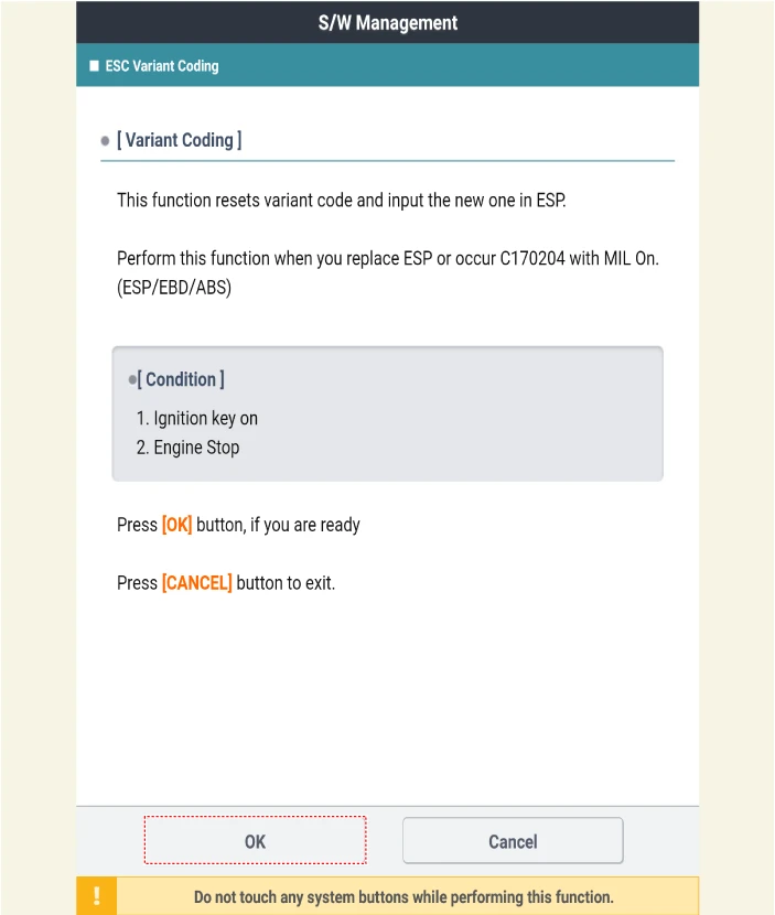
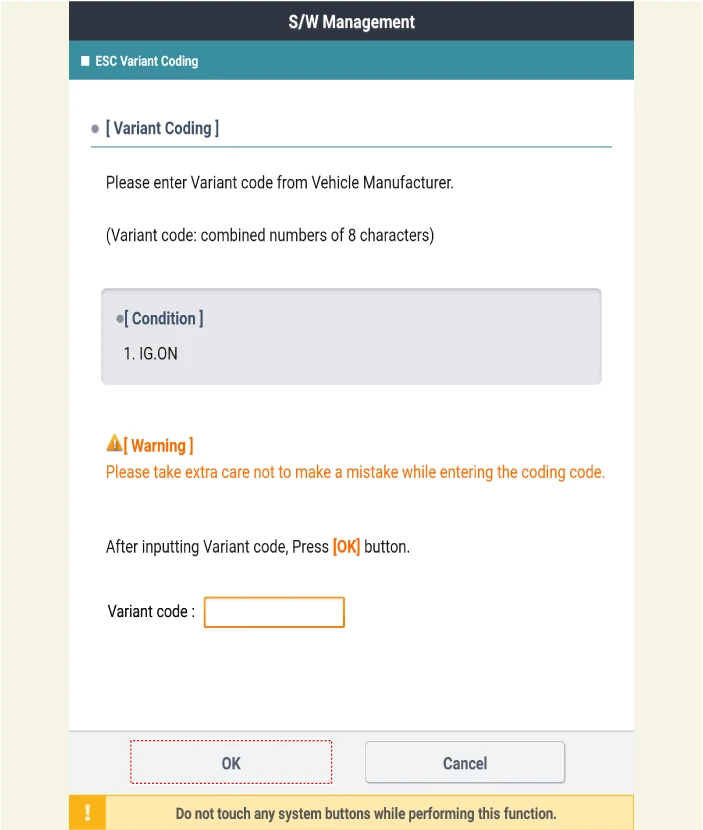
• Select the 'System Identification' on the S/W management menu and record the existing variant coding value, and after replacing the IEB, select the 'ESC Variant coding' on the menu and enter the recorded value.
1.Disconnect the battery negative ( - ) terminal and the service interlock connector.(Refer to Battery Control System - "Auxiliary 12 V Battery - 2WD")(Refer to Battery Control System - "Auxiliary 12 V Battery - 4WD")
2.Remove the Vehicle Control Unit (VCU).(Refer to Motor and Reduction Gear System - "Removal and Installation - 2WD")(Refer to Motor and Reduction Gear System - "Removal and Installation - 4WD")
3.Remove the reservoir tank.(Refer to Brake System - "Reservoir Tank - LHD")
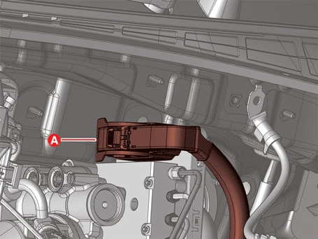
4.Disconnect the main connector (A).
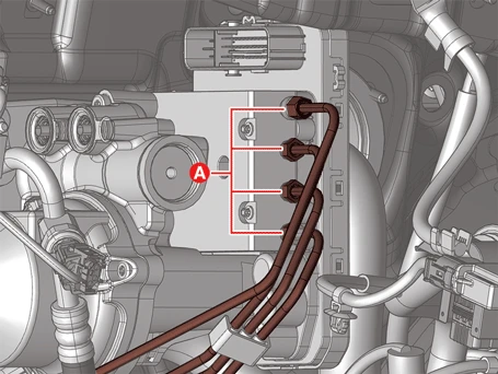
5.Separate the brake lines (A) after loosening the flare nuts.
Tightening torque :12.7 - 16.7 N·m (1.3 - 1.7 kgf·m, 9.4 - 12.3 lb·ft)

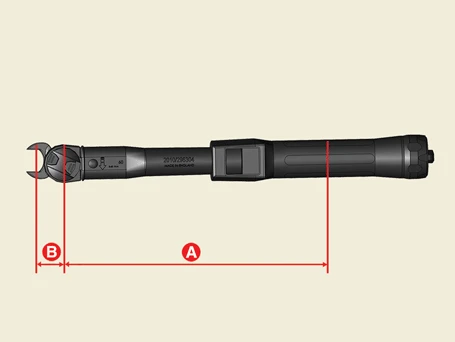
• If the extension wrench (A) is used to tighten the flare nut, refer to the below formula and calculate the true torque.
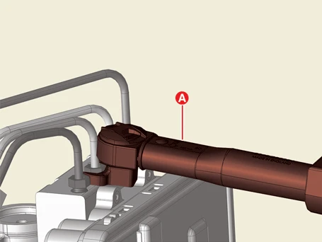
• True torque = Torque wrench dial reading
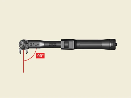
• True torque = [(A + B) / A] × Torque wrench reading
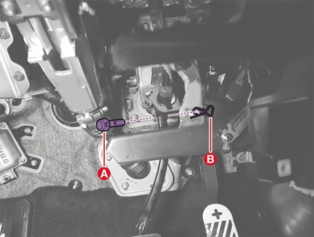
6.Remove the brake pedal arm mounting clevis pin (A) after removing the split pin (B).

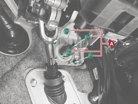
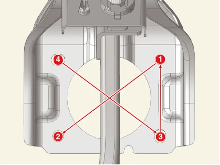
7.Remove the Integrated Electronic Brake (IEB) assembly nuts (A).
Tightening torque :12.7 - 17.7 N·m (1.3 - 1.8 kgf·m, 9.4 - 13.0 lb·ft)
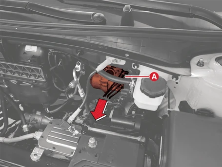
8.Remove the IEB (A).

Installation

• When working on high voltage system, the work should be carried by technicians who have completed the relevant training. It is because that lack of knowledge of the high voltage system can lead to serious accidents due to electric shock or electric leakage.
• When working on high voltage system or related system, make sure that you are familiar and comply with the "Safety Precautions, Cautions and Warnings." If you do not comply with the instructions, serious accidents due to electric shock or leakage may occur.
• When working on high voltage system, make sure to check the Personal Protective Equipment (PPE) and high voltage shut-off procedures.
1.Install in the reverse order of removal.

• Check the brake fluid level sensor is securely connected during installation, poor connection may cause the brake warning lamp to illuminate.
• Apply the grease when installing the brake pedal arm clevis pin (Grease type : GREASE PDLV-1)
• Be careful not to change the mounting position of the clevis pin and split pin.
• When transporting IEB, hold only (A) not the piston guard, operating rod, reservoir. And be careful not to damage the IEB.
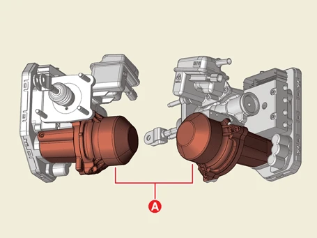

2.Fill the brake reservoir with brake fluid and perform the brake bleeding procedure.(Refer to Brake System - "Brake Bleeding Procedures")
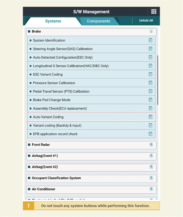
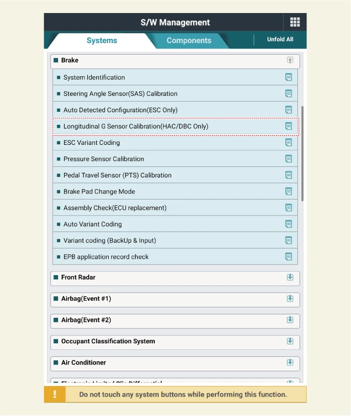
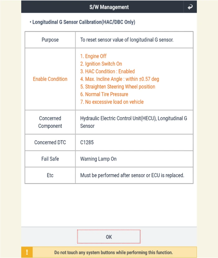
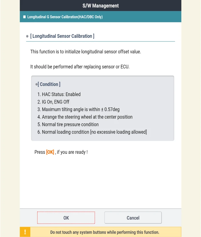
3.Perform the 'Auto Variant Coding', 'Variant Coding', 'Pressure sensor Calibration', 'Longitidinal G Sensor Calibration'.(Refer to Integrated Electronic Brake (IEB) - "Adjustment")
4.Perform the 'Pedal Travel Sensor (PTS) Calibration'.(Refer to Brake Pedal - "Adjustment")
Diagnostic procedure by using KDS
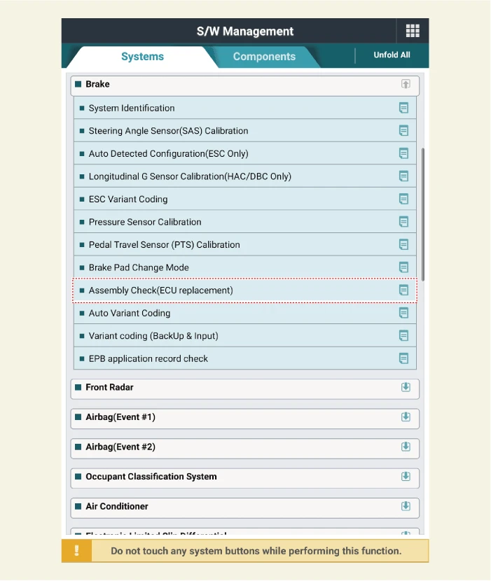
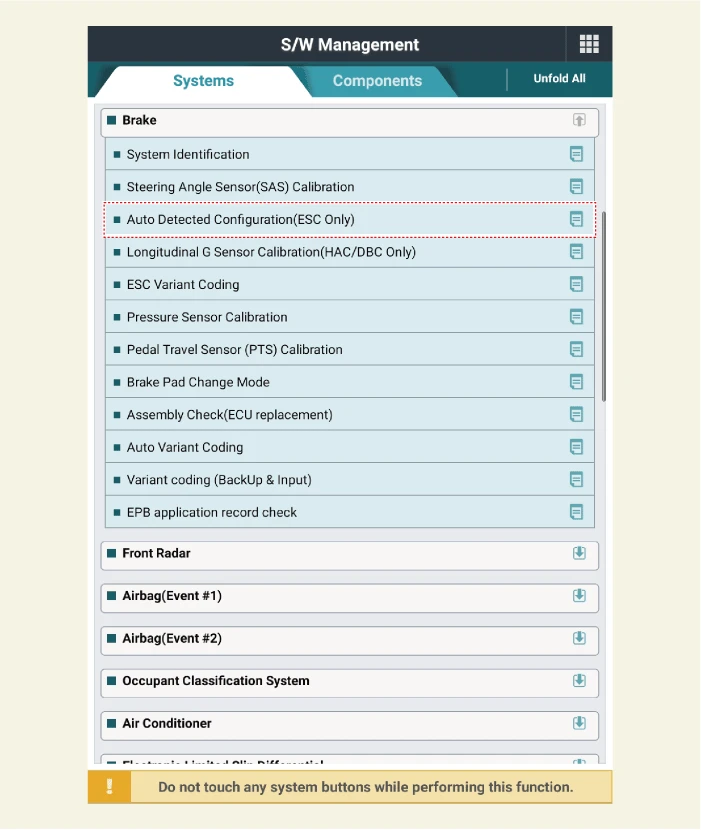
Perform diagnostic procedure by using KDS device as shown below:Connect self-diagnosis connector (16 pins) located under the driver side crash pad to self-diagnosis device, and then turn the self-diagnosis device after ignition is ON.Select the "vehicle model" and "Brake" on KDS vehicle selection screen, then select OK.[Auto Variant Coding]
[Variant Coding]
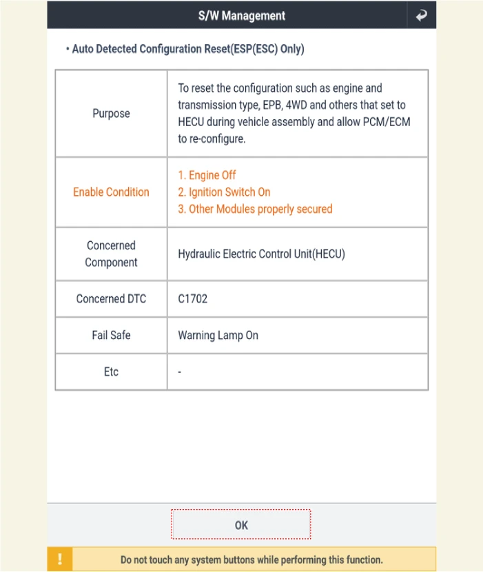
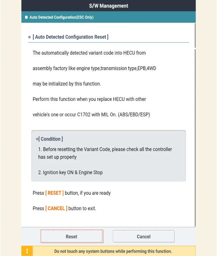
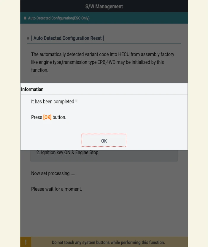
[Auto Detected Configuration]
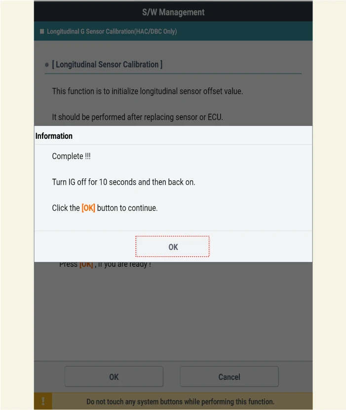
[Longitudinal G Sensor Calibration]
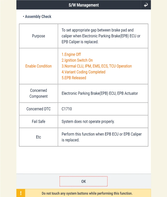
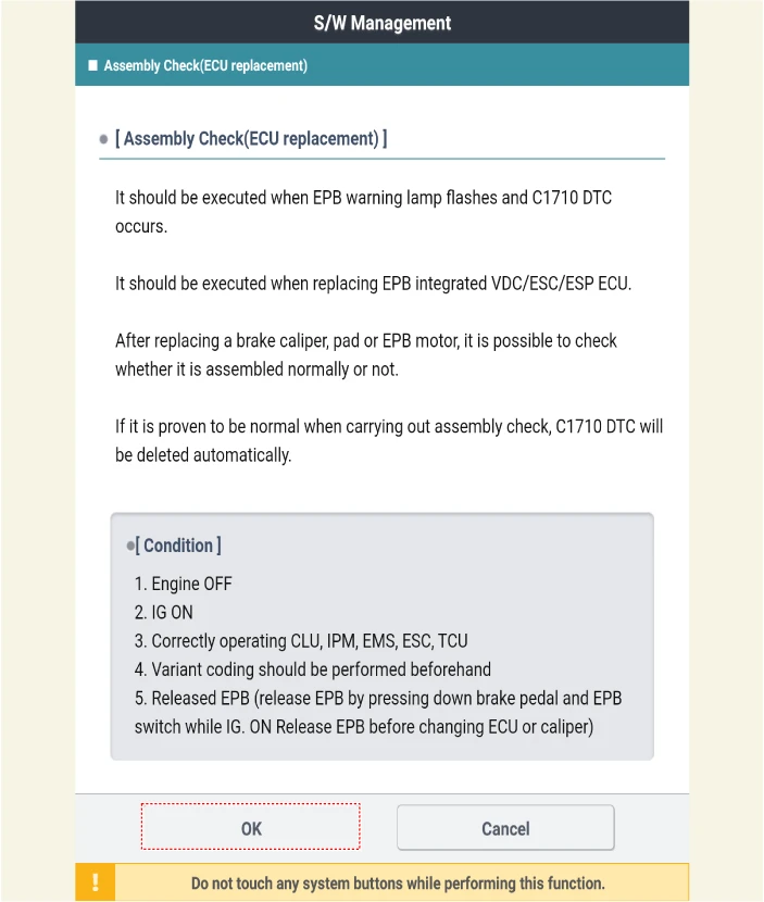
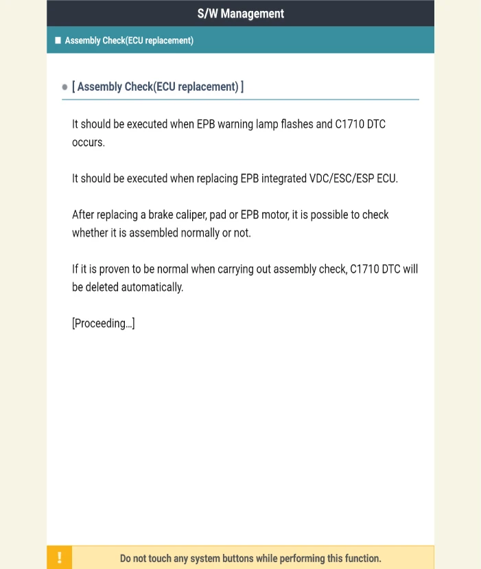
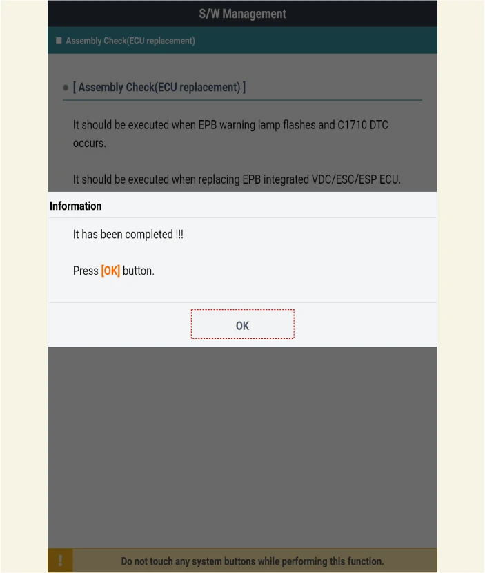
[Assembly Check]
