Description and Operation
The configuration of the heat pump functions to convert the flow of refrigerant to enable cooling and heating.This minimizes battery consumption during heating and improves the driving range of electric vehicles.EXV : Expansion valveSOL. : SolenoidTXV. : Thermal Expansion ValveCooling mode
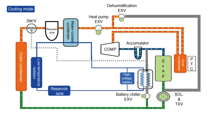
Cooling mode refrigerant flow sequence
1.An electric compressor compresses the refrigerant.
2.The compressed high-temperature, high-pressure refrigerant passes through the inner condenser. (there is no heat exchange with the vehicle interior)
3.The compressed high-temperature, high-pressure refrigerant passes through the heat pump EXV without expansion. (dehumidification EXV is closed)
4.The compressed high-temperature, high-pressure refrigerant transfers heat to the water-cooled condenser and is condensed.
5.Refrigerant 3-way valve opens toward outer condenser.
6.As the refrigerant passes through the outer condenser, it releases heat to the atmosphere and is further condensed.
7.Refrigerant expansion in SOL.-TXV. (solenoid valve open, EXV of high voltage battery chiller closed)
8.The expanded, low-temperature, low-pressure refrigerant absorbs heat from the vehicle interior in the evaporator.
9.Refrigerant that absorbs heat from inside the vehicle sends only gaseous refrigerant from the accumulator to the electric compressor.
Battery-only cooling mode
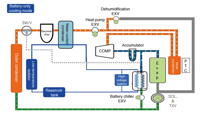
Battery-only cooling mode refrigerant flow sequence
1.An electric compressor compresses the refrigerant.
2.The compressed high-temperature, high-pressure refrigerant passes through the inner condenser. (there is no heat exchange with the vehicle interior)
3.The compressed high-temperature, high-pressure refrigerant passes through the heat pump EXV without expansion. (dehumidification EXV is closed)
4.The compressed high-temperature, high-pressure refrigerant transfers heat to the water-cooled condenser and is condensed.
5.Refrigerant 3-way valve opens toward outer condenser.
6.As the refrigerant passes through the outer condenser, it releases heat to the atmosphere and is further condensed.
7.Refrigerant expansion in battery chiller. (EXV duty control, SOL.&TXV solenoid valve closed)
8.The battery chiller absorbs heat from the high voltage battery and the refrigerant expands
9.Refrigerant that absorbs heat from inside the vehicle sends only gaseous refrigerant from the accumulator to the electric compressor.
Interior + battery cooling mode
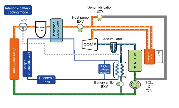
Interior + battery cooling mode refrigerant flow sequence
1.An electric compressor compresses the refrigerant.
2.The compressed high-temperature, high-pressure refrigerant passes through the inner condenser. (there is no heat exchange with the vehicle interior)
3.The compressed high-temperature, high-pressure refrigerant passes through the heat pump EXV without expansion. (dehumidification EXV is closed)
4.The compressed high-temperature, high-pressure refrigerant transfers heat to the water-cooled condenser and is condensed.
5.Refrigerant 3-way valve opens toward outer condenser.
6.As the refrigerant passes through the outer condenser, it releases heat to the atmosphere and is further condensed.
7.Refrigerant expansion in SOL.-TXV (solenoid valve open), Refrigerant expansion in battery chiller. (EXV duty control)
8.The expanded low-temperature, low-pressure refrigerant absorbs heat from the vehicle interior in the evaporator and absorbs heat from the battery coolant in the battery chiller.
9.Refrigerant that absorbs heat from inside the vehicle sends only gaseous refrigerant from the accumulator to the electric compressor.
Heating mode
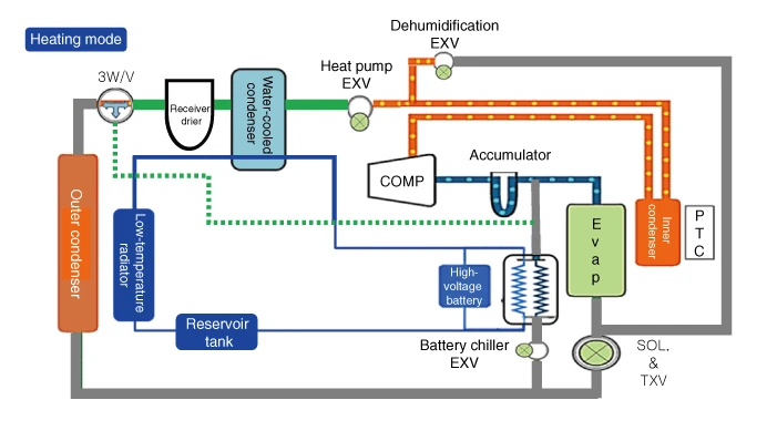
Heating mode refrigerant flow sequence
1.An electric compressor compresses the refrigerant.
2.When the compressed high-temperature and high-pressure refrigerant passes through the inner condenser, the mix door opens to the heating side to dissipate heat.
3.The compressed high-temperature, high-pressure refrigerant flows through a small hole in the heat pump EXV. (the dehumidification EXV is closed)
4.The expanded low-temperature and low-pressure refrigerant absorbs heat from the PE system in the water-cooled condenser.
5.Refrigerant 3-way valve opens in the direction of bypassing the outer condenser to minimize heat loss in the refrigerant.
6.Refrigerant that has absorbed heat from the drive PE system sends only gaseous refrigerant from the accumulator to the electric compressor.
Heating & dehumidification mode
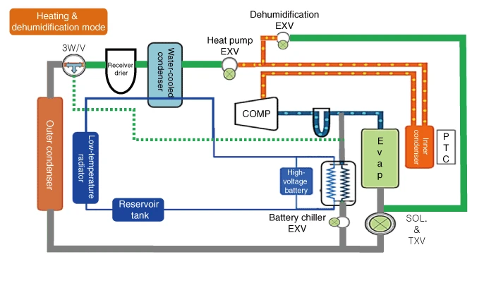
Heating & dehumidification mode refrigerant flow sequence
1.An electric compressor compresses the refrigerant.
2.When the compressed high-temperature and high-pressure refrigerant passes through the inner condenser, the mix door opens to the heating side to dissipate heat.
3.The compressed high-temperature, high-pressure refrigerant flows through a small hole in the heat pump EXV.
4.The dehumidification EXV opens and a portion of the expanded refrigerant passes through the evaporator to remove moisture from the room air.
5.The expanded low-temperature and low-pressure refrigerant absorbs heat from the PE system in the water-cooled condenser.
6.Refrigerant 3-way valve opens in the direction of bypassing the outer condenser to minimize heat loss in the refrigerant.
7.Refrigerant that has absorbed heat from the drive PE system sends only gaseous refrigerant from the accumulator to the electric compressor. (refrigerant that has been partially divided to dehumidify the indoor air is recombined)