Specification
| Item | Specification | |
| Ultrasonic sensor | Rated voltage (V) | 12 |
| Detecting range (cm / in.) | 30 ~ 120 | |
| Operation voltage (V) | 9 - 16 | |
| Operation current (mA) | MAX 350 | |
| Operation frequency (KHz) | 43 ~ 53 | |
| Sensor quantity | 8 units (Standard Type), 12 units (RSPA Type) | |
Description and Operation
System Operation Specification
Initial mode
1.PDW recognizes LIN ID and sets the sensor ID up during initialization.
2.When IBU initialization is completed, for 100 ms, the PDW will drive each sensor to perform fault diagnosis.
3.Fault diagnosis is completed, the sensor does not transmit fault information, and a PDW warning is issued.
4.If at least one front / rear sensor failure, display a fault warning.
5.The fault statement is displayed on the instrument cluster, and the fault symbol is displayed on both the instrument cluster and the audio / AVNT monitor.
Normal mode
1.The start of the normal routine after initialization begins after 100ms delay after completion of the alarm output.
2.The obstacle alarm has 3 levels in 1, 2 and 3 step levels; alarms 1 and 2 have intermittent audible sounds, while alarm 3 has continuous audible sound. For the front ultrasonic sensor level 1 alarm does not exist.
3.In the case of a cluster display, information from each sensor is transmitted from the IBU to the cluster.
4.The operating vehicle speed of the PDW is less than 10Km/h.
Removal

• When working on high voltage system, the work should be carried by technicians who have completed the relevant training. A lack of understanding of the high voltage system can lead to serious accidents due to electric shock or electric leakage.
• When working a high voltage system, the technician must be observed and aware of "High Voltage System General Safety Information and Caution". If not, it may cause serious accidents such as electric shock or short circuit.
• When working on high voltage system, make sure to check the Personal Protective Equipment (PPE) and high voltage shut-off procedures.
[Standard]
[Front Ultrasonic Sensor]
1.Disconnect the battery negative ( - ) terminal and the service interlock connector.(Refer to Battery Control System - "Auxiliary 12 V Battery - 2WD")(Refer to Battery Control System - "Auxiliary 12 V Battery - 4WD")
2.Remove the front bumper assembly.(Refer to Body - "Front Bumper Assembly")
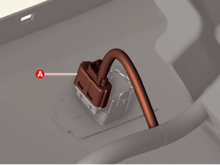
3.Disconnect the ultrasonic sensor connector (A).
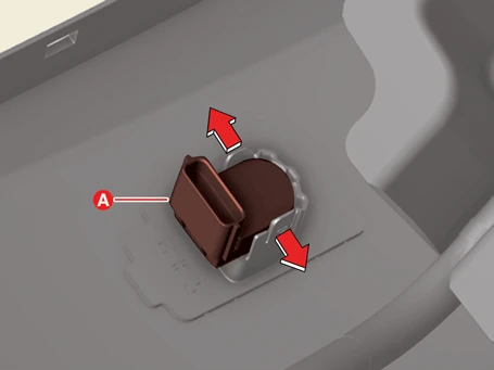
4.Remove the ultrasonic sensor (A) after pushing the sensor holder in the direction of arrow.
[Rear Ultrasonic Sensor]
1.Disconnect the battery negative ( - ) terminal and the service interlock connector.(Refer to Battery Control System - "Auxiliary 12 V Battery - 2WD")(Refer to Battery Control System - "Auxiliary 12 V Battery - 4WD")
2.Remove the rear bumper assembly.(Refer to Body - "Rear Bumper Assembly")
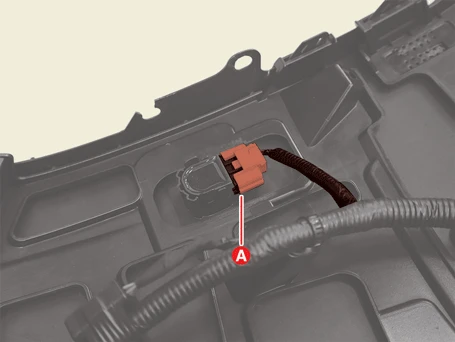
3.Disconnect the ultrasonic sensor connector (A).
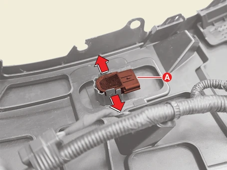
4.Remove the ultrasonic sensor (A) after pushing the sensor holder in the direction of arrow.
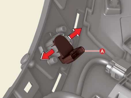
[Front Corner Ultrasonic Sensor (RSPA Only)]

1.Disconnect the battery negative ( - ) terminal and the service interlock connector.(Refer to Battery Control System - "Auxiliary 12 V Battery - 2WD")(Refer to Battery Control System - "Auxiliary 12 V Battery - 4WD")
2.Remove the front bumper assembly.(Refer to Body - "Front Bumper Assembly")
3.Disconnect the ultrasonic sensor connector (A).
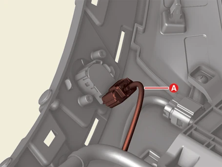
4.Remove the ultrasonic sensor (A) after pushing the sensor holder in the direction of arrow.
[Rear Corner Ultrasonic Sensor (RSPA Only)]

• RSPA : Remote Smart Parking Assist
1.Disconnect the battery negative ( - ) terminal and the service interlock connector.(Refer to Battery Control System - "Auxiliary 12 V Battery - 2WD")(Refer to Battery Control System - "Auxiliary 12 V Battery - 4WD")
2.Remove the rear bumper assembly.(Refer to Body - "Rear Bumper Assembly")
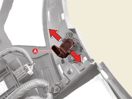
3.Disconnect the ultrasonic sensor connector (A).
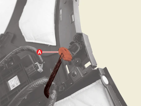
4.Remove the ultrasonic sensor (A) after pushing the sensor holder in the direction of arrow.
[Option]
[Front Ultrasonic Sensor]
1.Disconnect the battery negative ( - ) terminal and the service interlock connector.(Refer to Battery Control System - "Auxiliary 12 V Battery - 2WD")(Refer to Battery Control System - "Auxiliary 12 V Battery - 4WD")
2.Remove the front bumper assembly.(Refer to Body - "Front Bumper Assembly")
3.Disconnect the ultrasonic sensor connector (A).
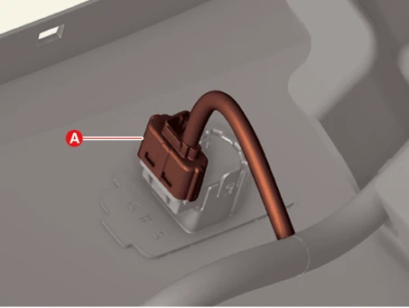
4.Remove the ultrasonic sensor (A) after pushing the sensor holder in the direction of arrow.
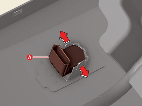
[Rear Ultrasonic Sensor - Side]
1.Disconnect the battery negative ( - ) terminal and the service interlock connector.(Refer to Battery Control System - "Auxiliary 12 V Battery - 2WD")(Refer to Battery Control System - "Auxiliary 12 V Battery - 4WD")
2.Remove the rear bumper assembly.(Refer to Body - "Rear Bumper Assembly")
3.Disconnect the ultrasonic sensor connector (A).
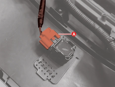
4.Remove the ultrasonic sensor (A) after pushing the sensor holder in the direction of arrow.
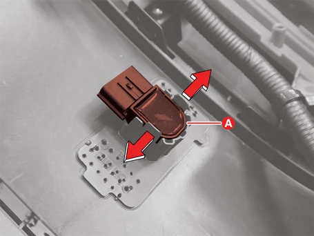
[Rear Ultrasonic Sensor - Center]
1.Disconnect the battery negative ( - ) terminal and the service interlock connector.(Refer to Battery Control System - "Auxiliary 12 V Battery - 2WD")(Refer to Battery Control System - "Auxiliary 12 V Battery - 4WD")
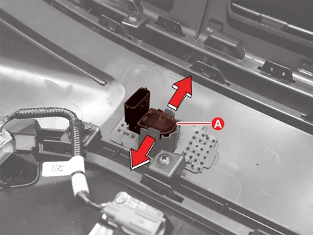
2.Remove the rear bumper beam assembly [GT - Line Type].(Refer to Body - "Rear Bumper Beam Assembly")
3.Disconnect the ultrasonic sensor connector (A).
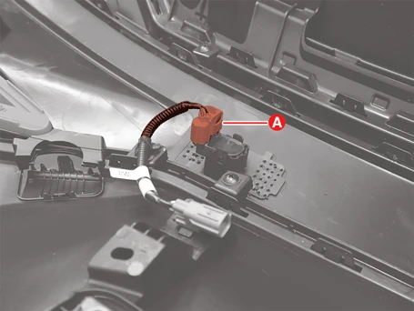
4.Remove the ultrasonic sensor (A) after pushing the sensor holder in the direction of arrow.
[Front Corner Ultrasonic Sensor (RSPA Only)]

1.Disconnect the battery negative ( - ) terminal and the service interlock connector.(Refer to Battery Control System - "Auxiliary 12 V Battery - 2WD")(Refer to Battery Control System - "Auxiliary 12 V Battery - 4WD")
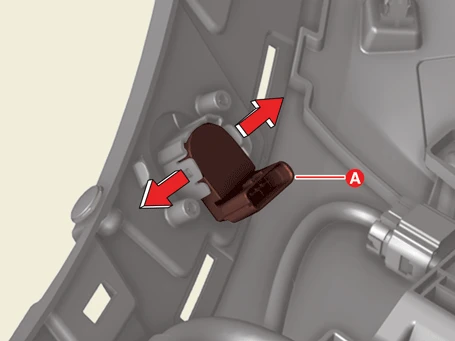
2.Remove the front bumper assembly.(Refer to Body - "Front Bumper Assembly")
3.Disconnect the ultrasonic sensor connector (A).
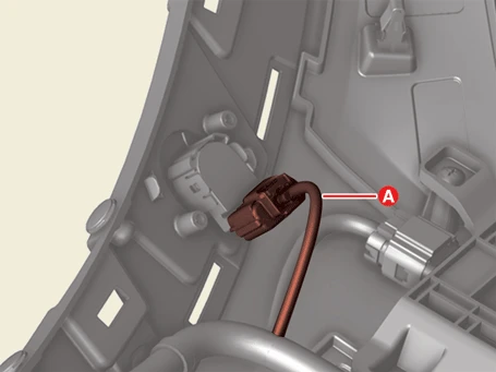
4.Remove the ultrasonic sensor (A) after pushing the sensor holder in the direction of arrow.
[Rear Corner Ultrasonic Sensor (RSPA Only)]

• RSPA : Remote Smart Parking Assist
1.Disconnect the battery negative ( - ) terminal and the service interlock connector.(Refer to Battery Control System - "Auxiliary 12 V Battery - 2WD")(Refer to Battery Control System - "Auxiliary 12 V Battery - 4WD")
2.Remove the rear bumper assembly [GT - Line Type].(Refer to Body - "Rear Bumper Assembly")
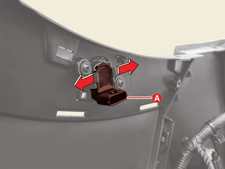
3.Disconnect the ultrasonic sensor connector (A).
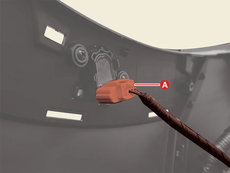
4.Remove the ultrasonic sensor (A) after pushing the sensor holder in the direction of arrow.
Installation

• When working on high voltage system, the work should be carried by technicians who have completed the relevant training. A lack of understanding of the high voltage system can lead to serious accidents due to electric shock or electric leakage.
• When working a high voltage system, the technician must be observed and aware of "High Voltage System General Safety Information and Caution". If not, it may cause serious accidents such as electric shock or short circuit.
• When working on high voltage system, make sure to check the Personal Protective Equipment (PPE) and high voltage shut-off procedures.
1.Install in the reverse order of removal.