Description and Operation
Function
1.Vehicle surrounding area video display function.
– The surrounding area video display function, displays 360° video image captured from four cameras on the audio / AVNT monitor screen while the vehicle is moving at low speed move forward or move backward.
2.Guide Line Indication & Steering Wheel Synchronized Feature.
– The Guide Line Indication & Steering Wheel Synchronized Feature is the function that assist the driver in parking by synchronizing the steering wheel with the rear view video display marked with a guide line to help anticipate the direction of the reversing vehicle.
– Neutral guidelines are fixed lines that are displayed regardless of steering wheel operation and are determined by the area of application of the vehicle.
3.Parking distance warning display function
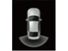
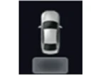
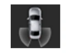
– It provides a function to display obstacle warning signals from ultrasonic sensors mounted in the fore and aft within the surround - view image so that the actual position of the sensors being warned can be checked when parked.
4.Tolerance calibration.
– Tolerance correction is intended to compensate for SVM deviations that may result from assembly line installation tolerances.
– To perform the correct tolerance calibration, the tolerance calibration environment must be constructed in compliance with the specified working environment.
SVM Mode Entry Conditions
The vehicle information is accessed regularly, even after entering SVM mode. When the conditions are met, conversion from front mode to rear mode is available, and vice versa.When the mode is converted, the view displayed on the screen can be the initial view or the previous view depending on the conditions.If the mode for conversion is the initial entry, the default view is selected based on the front or rear. If a continuous front - rear conversion mode occurs as forward and backward movement are repeated for parking, the previous view is recalled and displayed.– Initial Entry : When the rear and front view modes in SVM mode are displayed on the screen for the first time.
– Re - entry: When switching from SVM mode to another mode, without turning off SVM, and returning to the previous mode.(e.g. Rear → Front → Rear: Re - enter rear mode / Front → Rear → Front: Re - enter front mode)
| Switch mode | Vehicle speed | Gear range | SVM Switch | Display |
| Rear → Front | Below 10 km/h ( 6 mph) | "R" range or "P" range excluded | ON | Initial Entry: Front view set in the initial view mode option |
| Re - entry: The last view mode displayed in the previous front mode | ||||
| Front → Rear | Irrelevant | "R" range | Irrelevant | Initial Entry: Rear view set in the initial view mode option |
| Re - entry: The last view mode displayed in the previous rear mode |
SVM Mode Disengagement
If the conditions below are met while in SVM mode, the SVM is turned OFF and no video is displayed.1.Front modeWhen driving starts after turning on the Park / View button, the Park / View mode is automatically released at vehicle speeds of 10 km/h (6 mph) or higher.- With the Park / View button is 'OFF', When the gear is shifted to R, the SVM automatically operates, and then the gear changes to D, and the vehicle speed changes to 10km/h (6 mph) or more, it is automatically released.
2.Rear mode- It automatically turns off when any gear other than R is selected.
Operations for Guideline Steering Interlocking Indications
The guideline for steering interlocking trace is indicated by using the value of steering wheel angle periodically received by ADAS parking ECU via C-CAN.The rear area displayed in the rear mode image and the steering interlocking guideline are synthesized and displayed.1.View modes for guideline steering interlocking indications
| Mode | View | Remark |
| Rear | Rear View + Surround View |
|
| Rear Wide View + Surround View |
|
|
| Rear Side View + Surround View |
|
2.Specifications for guideline steering interlocking lines.
| Number | Distance | Color |
 |
0.5 m (19.6 in) | Red |
 |
1.0 m (39.3 in) | Yellow |
 |
3.0 m (118.1 in) | Yellow |
 |
Vehicle left side end + 0.3 m (11.8 in) | Yellow |
 |
Vehicle right side end + 0.3 m (11.8 in) | Yellow |
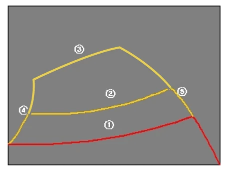
3.Neutral guidelines.When the steering angle is in the neutral state, the steering interlocking guideline indicating the expected trajectory of the vehicle is displayed in blue. It is a fixed line that is displayed together when outputting steering interlock guidelines and is not interlocked to steering angle operation.
Troubleshooting
1.Inspection by DTC Code
| Symptom | Suspected Cause | Correction |
| 1. Single DTC code appearance | Loose connector relevant to a certain DTC code. | Check connection status and reconnect the connector. |
| Tolerance calibration not completed |
1) DTC code appearance. 2) Perform tolerance calibration. |
|
| Disconnected wiring | Inspect for conductivity of relevant area of DTC and wiring. | |
| Faulty wiring connector |
Check for bent or damaged wiring connector pin. Inspect wiring. |
|
| Faulty ADAS Parking ECU connector |
1) Check for bent or damaged ADAS Parking ECU connector pin. 2) Replace ADAS Parking ECU. |
|
| Faulty ADAS Parking ECU or camera |
1) Check SVM basic operation and DTC on KDS. 2) Replace ADAS Parking ECU or camera. |
|
| 2. Multiple DTC codes appearance | Loosen ADAS Parking ECU main connector | Check connection status and reconnect the connector. |
| Disconnected wiring |
1) Camera power - In case of 6V or below, inspect relevant wiring. 2) ACC / IG power - In case of 7.5V or below, inspect relevant wiring. 3) SVM switch - In case of 1.75V or higher with the switch ON, inspect relevant wiring. |
|
| Faulty wiring connector |
1) Check for bent wiring connector pin or interference in neighboring parts. 2) Inspect wiring. |
|
| Faulty ADAS Parking ECU connector |
1) Check for bent ADAS Parking ECU connector or interference in neighboring
parts. 2) Replace ADAS Parking ECU. |
|
| Faulty ADAS Parking ECU or camera | If failure reoccurs after the items above are confirmed normal, replace ADAS Parking ECU or camera. |
2.Inspection for defect in SVM Performance (Image Output)
| Symptom | Suspected Cause | Correction |
|
1. No image output : Black screen, Blue screen |
Loose ADAS Parking ECU or camera main connector. | Check connection status and reconnect the connector. |
| Disconnected ADAS Parking ECU or camera wiring | Inspect for conductivity of ACC / IG / V-OUT / M-CAN terminal wiring. | |
| Faulty Integrated Central Control Unit (ICU) | Check power of ACC / IG terminals : In case of 7.5V or below, inspect Integrated Central Control Unit (ICU). | |
| Faulty ADAS Parking ECU or camera | If failure reoccurs after the items above are confirmed normal, replace ADAS Parking ECU or camera. | |
|
2. Abnormal image output : Noise on screen / lines / cracked display / unable to change display |
Loose main connector | Check connection status and reconnect the connector. |
| Disconnected or short - circuited wiring | Inspect for conductivity of relevant area of DTC and wiring. | |
| Faulty tolerance calibration | If the SVM image display is cracked even though the camera display is normal, execute tolerance calibration again. | |
| Faulty camera | If both camera display and SVM image display are cracked, inspect the camera. | |
| Faulty ADAS Parking ECU | Inspect Integrated Central Control Unit (ICU). | |
| Faulty console switch |
Inspect SVM switch. - In case of 1.75V or higher with the switch ON, replace the switch. |
|
| Faulty ADAS Parking ECU or camera | If failure reoccurs after the items above are confirmed normal, replace ADAS Parking ECU or camera. |
3.Inspection for Faulty PDW Warning Display & Parking Guideline
| Symptom | Suspected Cause | Correction |
| Faulty PDW warning display & faulty parking guideline | AVN option information not configured | Check and modify AVN option configuration status. |
| Loose main connector | Check connection status and reconnect the connector. | |
| Faulty Integrated Central Control Unit (ICU) |
1) Check that Parking Distance Warning (PDW) and Steering wheel Angle Sensor
(SAS) are normal. 2) Inspect Integrated Central Control Unit (ICU). |
|
| Faulty ADAS Parking ECU | If failure reoccurs after the items above are confirmed normal, replace ADAS Parking ECU. |
Removal

• When working on high voltage system, the work should be carried by technicians who have completed the relevant training. A lack of understanding of the high voltage system can lead to serious accidents due to electric shock or electric leakage.
• When working a high voltage system, the technician must be observed and aware of "High Voltage System General Safety Information and Caution". If not, it may cause serious accidents such as electric shock or short circuit.
• When working on high voltage system, make sure to check the Personal Protective Equipment (PPE) and high voltage shut-off procedures.

Front View Camera
1.Disconnect the battery negative ( - ) terminal and the service interlock connector.(Refer to Battery Control System - "Auxiliary 12 V Battery - 2WD")(Refer to Battery Control System - "Auxiliary 12 V Battery - 4WD")
2.Remove the front bumper assembly.(Refer to Body - "Front Bumper Assembly")
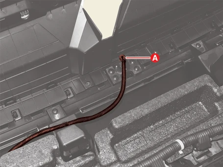
3.Disconnect the front view camera connector (A).
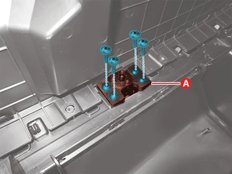
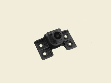
4.Remove the front view camera (A) after removing the screws.
Side View Camera [LH / RH]
1.Disconnect the battery negative ( - ) terminal and the service interlock connector.(Refer to Battery Control System - "Auxiliary 12 V Battery - 2WD")(Refer to Battery Control System - "Auxiliary 12 V Battery - 4WD")
2.Remove the mirror housing cover.(Refer to Body - "Outside Rear View Mirror")
3.Remove the side view camera (A).
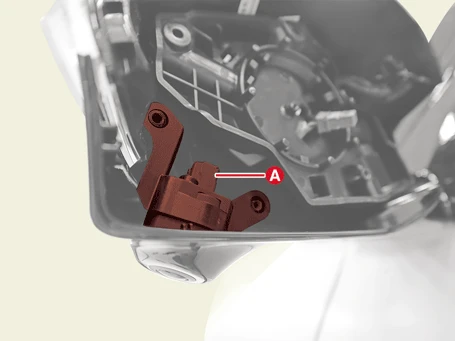
4.Disconnect the side view camera connector (A).
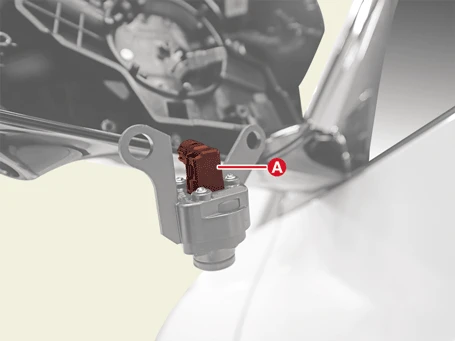
Rear View Camera
1.Disconnect the battery negative ( - ) terminal and the service interlock connector.(Refer to Battery Control System - "Auxiliary 12 V Battery - 2WD")(Refer to Battery Control System - "Auxiliary 12 V Battery - 4WD")
2.Remove the rear view camera.(Refer to Advanced Driver Assistance System Parking - "Rear View Monitor (RVM)")
Installation

• When working on high voltage system, the work should be carried by technicians who have completed the relevant training. A lack of understanding of the high voltage system can lead to serious accidents due to electric shock or electric leakage.
• When working a high voltage system, the technician must be observed and aware of "High Voltage System General Safety Information and Caution". If not, it may cause serious accidents such as electric shock or short circuit.
• When working on high voltage system, make sure to check the Personal Protective Equipment (PPE) and high voltage shut-off procedures.
1.Install in the reverse order of removal.
2.Installation the SVM camera, perform manual tolerance calibration.(Refer to Surround View Monitor (SVM) - "Adjustment")

• After replacing ADAS Parking ECU, always check that the system operates properly.
• If the failure still exists after replacing the ADAS Parking ECU, do not replace the unit.
Adjustment
Tolerance Calibration Outline.

• SVM calibration tool is required to perform tolerance calibration as shown below.
• Tolerance calibration compensates for the error margins of surround view video that occur due to the installation tolerance when the four cameras that comprise the SVM system are installed.

– When removing and installing a SVM camera.
– When conducting a body task such as the trunk task that causes the focus of the SVM camera to change.
– When replacing the outside rear view mirror with a SVM camera.
– When replacing the ADAS Parking ECU.
Tolerance Calibration Environments
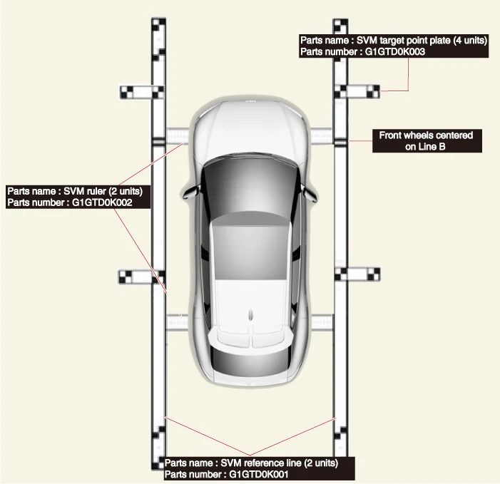
Manual Tolerance Calibration Procedure
1.Prepare in advance as below.
– Confirm that the car hood, trunk and doors are closed.
– Close the door after getting in on the driver side.
– Maintain IG ON.
– Unfold outside rear view mirrors.
– Shift the gear to N.
– During the advance preparation, do not install exhaust inhaler or other equipment that may block the view of rearview cameras.
– Engage foot brake and electronic parking brake (EPB) to hold vehicle in place.
2.Before entering tolerance calibration mode, to check normal operation of SVM ECU and cameras, perform the following.
– Check that initial setting screen of SVM is displayed. (Front view image + surround view image when shifted to N)
– Check that front, rear, left and right images of surround view monitor are properly displayed.
– If images are properly displayed, enter tolerance calibration mode. Otherwise, if images are abnormally displayed or are not displayed, replace relevant part.
3.Install two calibration scales, two calibration reference line boards, and four calibration target boards around the vehicle by referring to the manual provided with the tools.

• There are two types of calibration reference line boards (Type A & B) and the base line should be matched to vehicle type.
• Accurately set the location (distance / angle) of the center of white and black calibration board as this is the reference point.
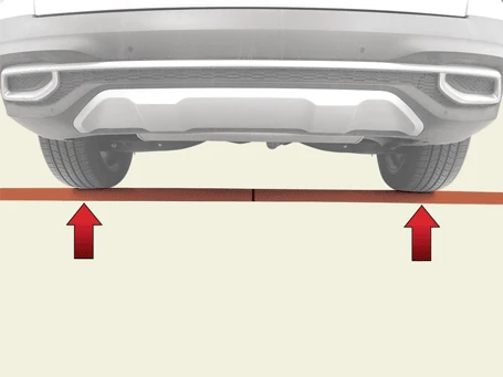
(1)Align the vehicle in a straight line and install the SVM ruler on the front and rear tires in the direction of the arrow.
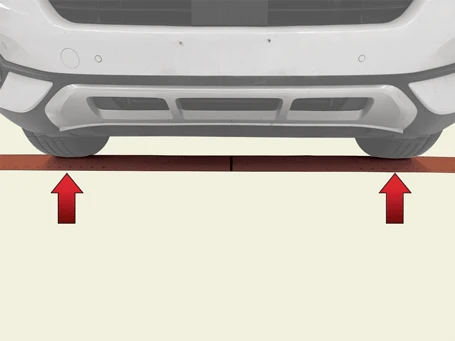
(2)To align the center point of the vehicle, install the calibration ruler by moving it from side to side so that the calibration ruler dimensions below the tires on the right and left sides are the same.

• Be careful not to crease when installing the SVM ruler.
• The measurements on both sides should be the same.
[RH]
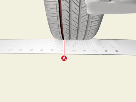
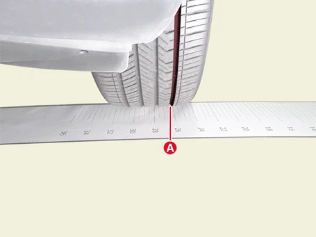
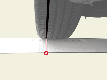
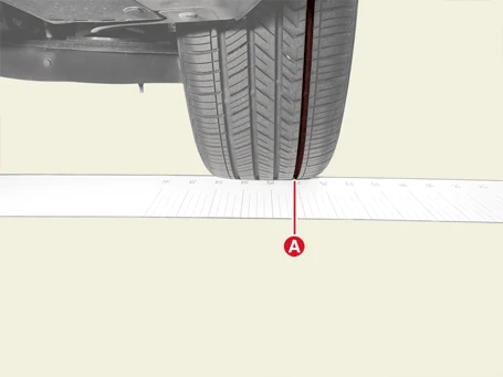

• If the vehicle is equipped with tires of different dimensions than the specification, the results of the SVM tolerance correction work may not be accurate.
• The dimensions of the front and rear tires may be different.
(3)The SVM reference line should be installed according to the end point of SVM ruler.

• Align the right - front wheel center of the tire with the base line on the SVM reference line.
• There are two types of calibration reference line boards (Type A & B) and the Base line should be matched to vehicle type.
• Base line margin of error should be 3 cm (1.1 in)
• Measure the margin of error at the end of the baseline.
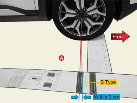

• Install it in the same way on the left hand side.
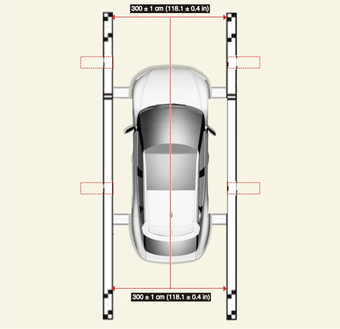
(4)After installing the calibration ruler and the calibration reference line, verify that the left and right calibration reference lines are installed parallel to each other.

• If the distance between left and right is the same back and forth, the calibration reference line is normally installed.
• The error range of the calibration reference line left / right distance shall be 299 ~ 301 cm (117.7 ~ 118.5 in).
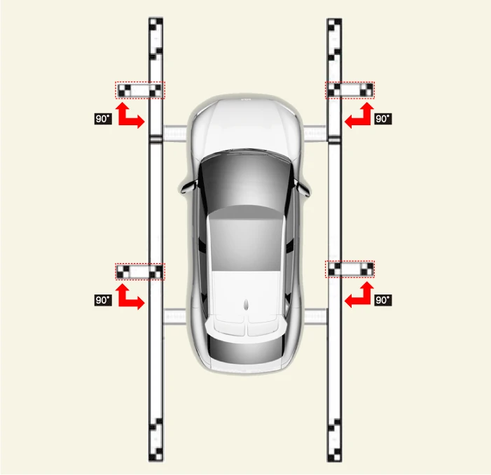
(5)Install the SVM target on the SVM reference line.

• The angle between the SVM calibration reference line and the SVM calibration target shall be 90 degrees.
• Rotation error when aligning vehicle should be within 1° to left / right.
4.Maintain IG ON with vehicle stopped, check that the gear is in N, and engage parking brake even on flat ground.
5.Perform work with SVM switched "ON".
6.Perform SVM manual tolerance calibration by using the KDS.
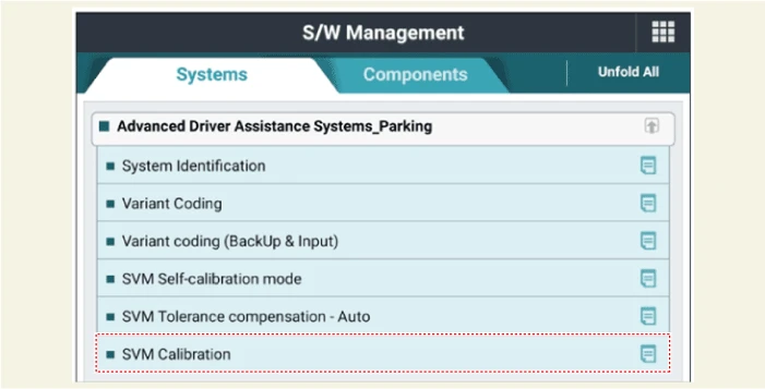
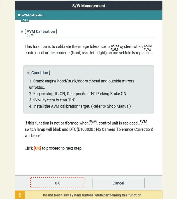
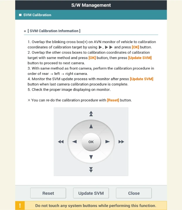

• Before matching calibration points: "+" green light flashes.
• When clicking [OK] after matching calibration points: "+" red light ON.
• After matching the four front calibration points, click the OK button and click the Update SVM button to move to the next camera calibration.
• Perform calibration tasks in the order of the front -> rear -> left -> right camera.
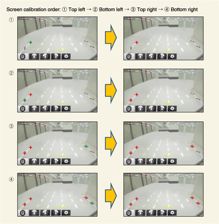
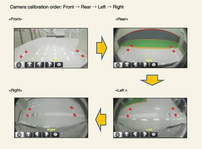
7.Check the vehicle and the calibration line on the monitor screen to see if the calibration has been completed normally and press the [OK] button.If calibration has not been properly performed, click [Cancel] and reenter calibration points.
[AVN Monitor Screen]
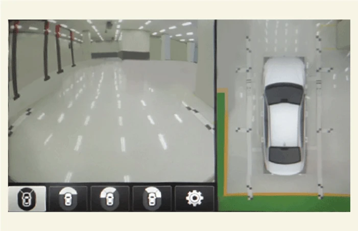

• Do not fold and store the calibration ruler, calibration reference line, calibration target.
• Clean any debris found on the SVM rulers, SVM reference lines or the target point before storing them in their container.
• The calibration ruler, calibration reference line, and calibration target are rolled into the enclosed cylindrical roll and stored in a dedicated storage bag.
Automatic Tolerance Calibration While Driving
1.Check the following conditions for normal operation of the automatic tolerance calibration while driving.
– Check whether the front / rear / left / right sides of the SVM top view are displayed normally.
– If the image is not displayed normally, check the related parts.

• Automatic tolerance calibration while driving should only be done when it is inevitable, such as when there is no equipment.
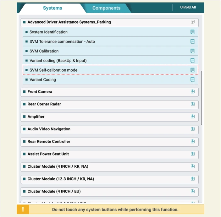
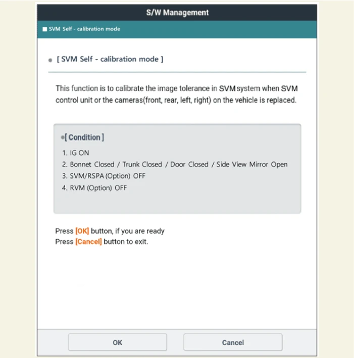
1.Perform the 'SVM Self-calibration mode' using KDS.
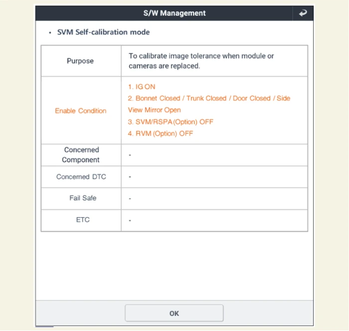
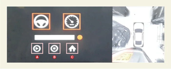
2.Check the steering angle (A), vehicle speed (B) and SVM top view (C) are displayed normally on the dealer mode screen.
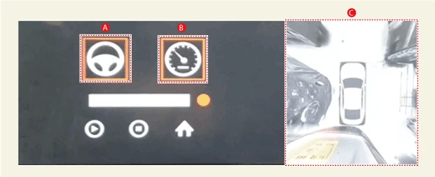

• After entering the automatic tolerance correction while driving, the diagnostic device entry mode can be terminated by manipulating the MAP and MEDIA buttons.
• The operating conditions for automatic tolerance correction while driving are steering wheel steering angle -5 ~ 5° and vehicle speed1 ~ 50 km/h (0.6 ~ 31 mph)
• When a vehicle is out of the steering angle or vehicle speed the steering wheel symbol (A) and the speed meter symbol (B) are displayed in red and if the vehicle meets the requirements, they will be displayed in green.
• Tolerance calibration is performed only when both the steering wheel symbol and the speedometer symbol are marked in green.
3.Move a vehicle to road and select the start button (A) on the dealer mode screen to perform the tolerance calibration while maintaining constant speed.
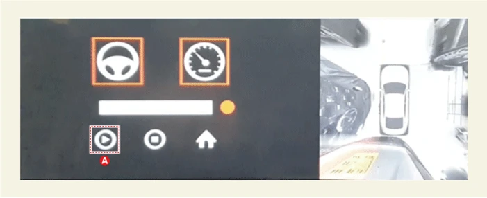

• When the steering wheel angle and speed conditions are met, a green border is expressed on each symbol and calibration is initiated.
• If the top view is inconsistent after the calibration is completed, press the start button (A) to re - run.

• Ideal road conditions for tolerance calibration while driving.
– The center lane of a one - way three - lane road with markers such as arrows, letters, etc. on the road surface.
– A flat road which is not uphill / downhill and without slope.
• Factors that can cause temporary stop or delay of tolerance calibration while driving.
– Road / environment without feature points.
– Nighttime, rainfall, snowfall environment.
– Painted indoor parking lot.
• Correctable camera distortion limit.
– Yaw : -5 ~ 5°
– Roll : -5 ~ 5°
– Pitch : -5 ~ 5°
4.The calibration progress rate while driving can be checked with the status bar (A).
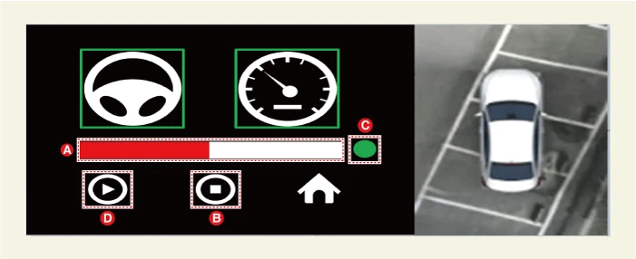

• The indicator (C) on the dealer mode screen blinks in green during calibration.
• It is possible to drive freely without restrictions on the steering angle and vehicle speed while the calibration is in progress after entering the calibration.
• The calibration time takes about 2 minutes under ideal conditions.
• When a start button (D) is pressed during calibration, it can resume from the point of stop after pause.
• If the stop button (B) is pressed during calibration, it can be stopped, and if the start button (D) is pressed again, it can be started from the beginning.
• When the status bar is filled fully, calibration is completed and the signal light (C) is displayed in green.
5.Check the calibration result when the calibration is completed.Criteria to determine the calibration result : The distortion of the mating surface area at a distance of 1.8 m (5.9 ft.) from a vehicle must be within 8 cm (3.15 in.).
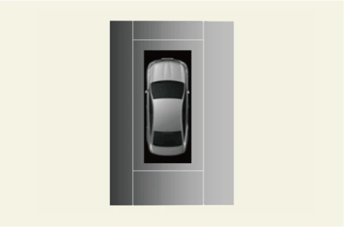
6.Press the Home button (C) at the end of the calibration function. (The AVN monitor automatically reboots at the end of the calibration function)

• Do not operate the audio / AVNT monitor button if a pop - up 'Update in progress' occurs during reboot.
• To check the calibration results, we recommend a flat and precisely divided parking lot.
• If the calibration result is not met, perform the automatic tolerance calibration again while driving.
– If additional calibration is needed after the saved calibration result, select the start button (A) to perform it again.
– After deleting the saved result by selecting the stop button (B), perform the new calibration by selecting the start button (A).
