Component
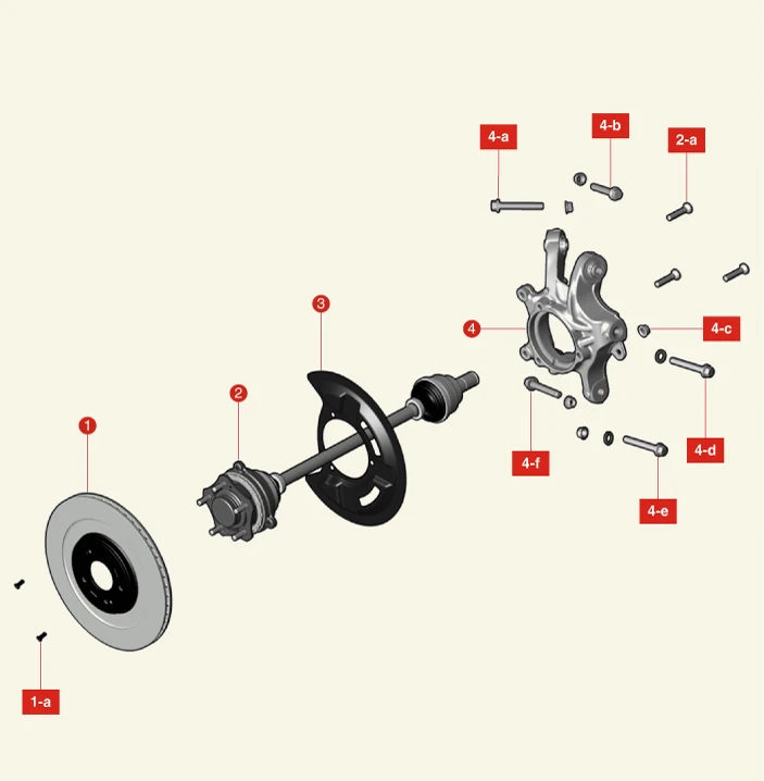
1. Rear Brake Disc
1-a. 4.9 - 5.9 N·m (0.5 - 0.6 kgf·m, 3.6 - 4.3 lb·ft)
2. Integrated Drive Axle (IDA)
2-a. 127.5 - 147.1 N·m (13.0 - 15.0 kgf·m, 94.0 - 108.5 lb·ft)
3. Rear Dust Cover
4. Rear Carrier
4-a. 156.9 - 176.5 N·m (16.0 - 18.0 kgf·m, 115.7 - 130.2 lb·ft)
4-b. 156.9 - 176.5 N·m (16.0 - 18.0 kgf·m, 115.7 - 130.2 lb·ft)
4-c. 98.1 - 117.7 N·m (10.0 - 12.0 kgf·m, 72.3 - 86.8 lb·ft)
4-d. 117.7 - 137.3 N·m (12.0 - 14.0 kgf·m, 86.8 - 101.3 lb·ft)
4-e. 176.5 - 196.1 N·m (18.0 - 20.0 kgf·m, 130.2 - 144.7 lb·ft)
4-f. 117.7 - 137.3 N·m (12.0 - 14.0 kgf·m, 86.8 - 101.3 lb·ft)
Removal

• When working on high voltage system, the work should be performed by technicians who have completed the relevant training. It is because that lack of knowledge of the high voltage system can lead to serious accidents due to electric shock or electric leakage.
• When working on high voltage system or related system, make sure that you are familiar and comply with the "Safety Precautions, Cautions and Warnings." If you do not comply with the instructions, serious accidents due to electric shock or leakage may occur.
• When working on high voltage system, make sure to check the Personal Protective Equipment (PPE) and high voltage shut-off procedures.
1.Disconnect the battery negative ( - ) terminal and the service interlock connector.(Refer to Battery Control System - "Auxiliary 12 V Battery - 2WD")(Refer to Battery Control System - "Auxiliary 12 V Battery - 4WD")
2.Remove the rear wheel and tires.(Refer to Suspension System - "Wheel")
3.Remove the rear under cover.(Refer to Rear Motor and Reduction Gear System - "Rear Under Cover")
4.Remove the rear brake disc.(Refer to Brake System - "Rear Brake Disc")
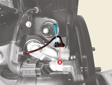
5.Remove the rear wheel speed sensor (A) after removing the bolt.
Tightening torque :8.8 - 13.7 N·m (0.9 - 1.4 kgf·m, 6.5 - 10.1 lb·ft)
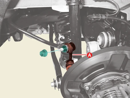
6.Separate the stabilizer bar link (A) after removing the nut.
Tightening torque :98.1 - 117.7 N·m (10.0 - 12.0 kgf·m, 72.3 - 86.8 lb·ft)

7.Separate the rear assist arm (A) after removing the the bolt, nut, and washer.
Tightening torque :117.7 - 137.3 N·m (12.0 - 14.0 kgf·m, 86.8 - 101.3 lb·ft)
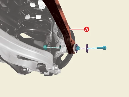

• Install the transmission jack and lift up the parts to prevent the bolts and nuts from damage when installing or removing.
• Be careful not to change the position of the bolt, nut, and washer when installing.

8.Separate the trailing arm (A) after removing the bolt and nut.
Tightening torque :117.7 - 137.3 N·m (12.0 - 14.0 kgf·m, 86.8 - 101.3 lb·ft)
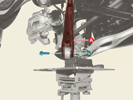

• Install the transmission jack and lift up the parts to prevent the bolts and nuts from damage when installing or removing.
• Be careful not to change the position of the bolt, nut, and washer when installing.

9.Separate the rear upper arm - front (A) after removing the bolt and nut.
Tightening torque :156.9 - 176.5 N·m (16.0 - 18.0 kgf·m, 115.7 - 130.2 lb·ft)
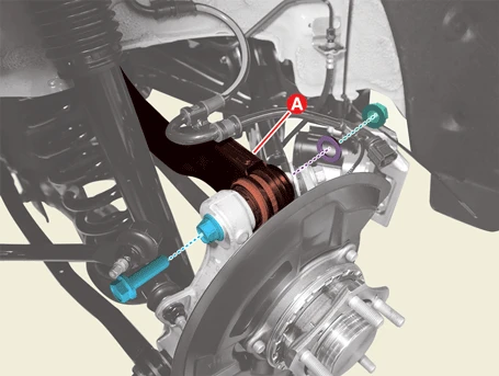

• Install the transmission jack and lift up the parts to prevent the bolts and nuts from damage when installing or removing.
• Be careful not to change the position of the bolt, nut, and washer when installing.

10.Separate the rear upper arm - rear (A) after removing the bolt, nut, and washer.
Tightening torque :156.9 - 176.5 N·m (16.0 - 18.0 kgf·m, 115.7 - 130.2 lb·ft)
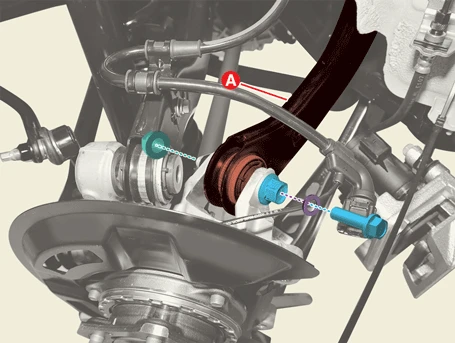

• Install the transmission jack and lift up the parts to prevent the bolts and nuts from damage when installing or removing.
• Be careful not to change the position of the bolt, nut, and washer when installing.

11.Separate the rear lower arm (A) after removing the bolt, nut, and washer.
Tightening torque :176.5 - 196.1 N·m (18.0 - 20.0 kgf·m, 130.2 - 144.7 lb·ft)
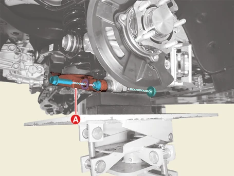

• Install the transmission jack and lift up the parts to prevent the bolts and nuts from damage when installing or removing.
• Be careful not to change the position of the bolt, nut, and washer when installing.

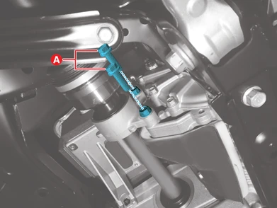
12.Remove the inner shaft bearing bracket bolts (A). [LH]
Tightening torque :63.7 - 70.6 N·m (6.5 - 7.2 kgf·m, 47 - 52.1 lb·ft)
13.Remove the rear carrier and Integrated Drive Axle (IDA) (A).
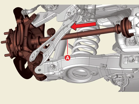

• Do not pull the wheel side axle when removing IDA, damage to the inside of the reduction gear may occur, pull the joint cup (A).
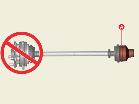
• When carrying IDA, hold the shaft or both side joints.
• Do not insert the pry bar too deep, as this may damage the oil seal.
• Removing the driveshaft using excessive force may damage the boot or bearing.
• Plug the hole of the reduction gear case with the oil seal cap to prevent contamination.
• Replace the retainer ring each time the drive shaft is removed.
14.Remove the rear stabilizer bar link (A) after removing the nut..
Tightening torque :98.1 - 117.7 N·m (10.0 - 12.0 kgf·m, 72.3 - 86.8 lb·ft)
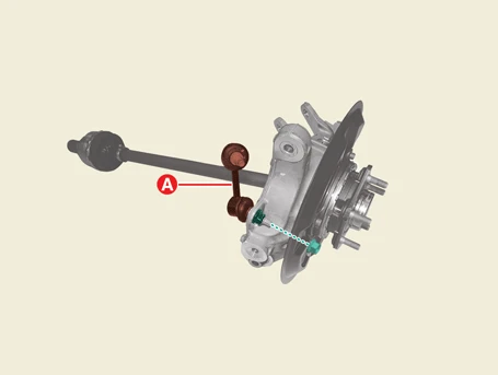
15.Remove the IDA mounting bolts (A).
Tightening torque :127.5 - 147.1 N·m (13.0 - 15.0 kgf·m, 94.0 - 108.5 lb·ft)
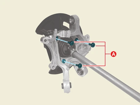
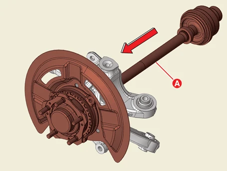
16.Remove the IDA and rear dust cover (A).
Installation
1.Install in the reverse order of removal.
2.Check the alignment.(Refer to Suspension System - "Alignment")
Inspection
1.Check the rear carrier for cracks.