Component
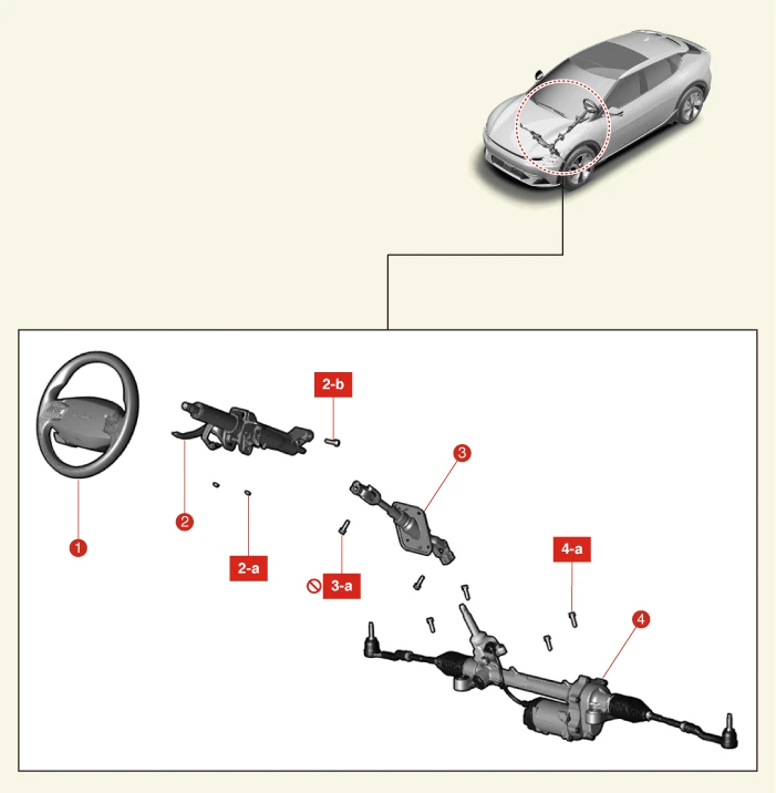
1. Steering Wheel
2. Steering Column Assembly
2-a. 24.5 - 29.4 N·m (2.5 - 3.0 kgf·m, 18.1 - 21.7 lb·ft)
2-b. 53.9 - 58.8 N·m (5.5 - 6.0 kgf·m, 39.8 - 43.4 lb·ft)
3. Universal Joint
3-a. 49 - 58.8 N·m (5.0 - 6.0 kgf·m, 36.2 - 43.4 lb·ft)
4. Steering Gear Box
4-a. 107.9 - 127.5 N·m (11.0 - 13.0 kgf·m, 79.6 - 94 lb·ft)
On Vehicle Inspection
1.Check the steering column for damage and deformation.
2.Check the joint bearing for damage and wear.
3.Check the tilt bracket for damage and cracks.
Removal
Column and shaft assembly
1.Align the steering wheel straight.
2.Secure the steering wheel to prevent movement.

3.Disconnect the battery negative ( - ) terminal and the service interlock connector.(Refer to Battery Control System - "Auxiliary 12 V Battery - 2WD")(Refer to Battery Control System - "Auxiliary 12 V Battery - 4WD")
4.Remove the front trunk.(Refer to Body - "Front Trunk")
5.Separate the steering universal joint from the steering gear box.
(1)Remove the steering universal joint bolt (A).
Tightening torque :49.0 - 58.8 N·m (5.0 - 6.0 kgf·m, 36.2 - 43.4 lb·ft)
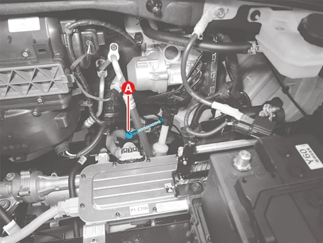

(2)Separate the steering universal joint (A) in the direction of the arrow.
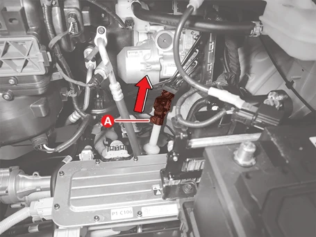
6.Remove the multi function switch.(Refer to Body Electrical System - "Multifunction Switch")
7.Remove the knee air bag.(Refer to Restraint (Airbag(Event #1)) - "Knee Airbag (KAB) Module")

8.Remove the wiring clip (A).
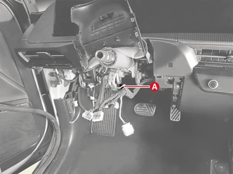
9.Remove the steering column assembly dust cover nuts (A).
Tightening torque :12.7 - 17.7 N·m (1.3 - 1.8 kgf·m, 9.4 - 13 lb·ft)
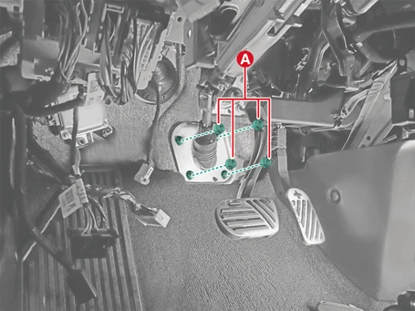
10.Remove the column and shaft assembly (A) after removing the bolt and nuts.
Tightening torque :Nut : 24.5 - 29.4 N·m (2.5 - 3.0 kgf·m, 18.1 - 21.7 lb·ft)Bolt : 53.9 - 58.8 N·m (5.5 - 6.0 kgf·m, 39.8 - 43.4 lb·ft)
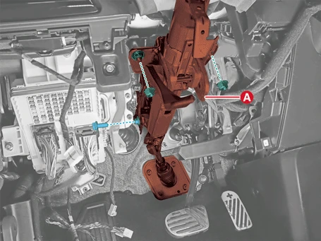
Installation
1.Install in the reverse order of removal.

• Tighten the bolts and nuts to the specified torque.
• When assembling the steering column, insert the dowel pin (A) well into the MDPS bracket groove (B).
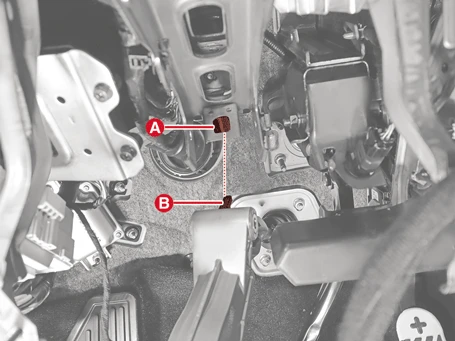
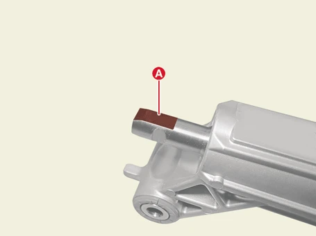
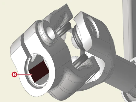
• Tighten the steering gear joint by firmly inserting it into the steering gearbox pinion shaft during installation.
• Make sure that the head of the universal joint mounting bolt is mounted facing the driver.
2.Perform the Steering Angle Sensor (SAS) Calibration.(Refer to Motor Power Steering System - "Adjustment)
Disassembly
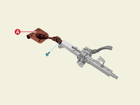
1.Separate the universal joint assembly (A) after removing the bolt.
Tightening torque :49.0 - 58.8 N·m (5.0 - 6.0 kgf·m, 36.2 - 43.4 lb·ft)

Reassembly
1.Reassemble in the reverse order of disassembly.

• Tighten the bolts and nuts to the specified torque.
• Make sure that the mounting bolt groove (A) is aligned when assembling.
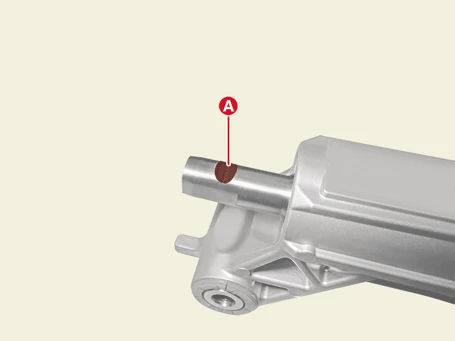
• Match the column assembly face (A) with the joint assembly face (B) when assembling.
