Description
Motor position sensor
Accurate motor rotor absolute position detection is required for motor control.The MCU can control the motor under optimal conditions using the position and speed of the rotor transmitted from the resolver. The resolver is mounted on a rear plate and consists of the rotor connected with motor rotor, and stator connected with housing. This locates the position of the rotor inside the motor, like the CMP sensor of the ICE vehicle.Motor temperature sensor
The motor temperature sensor is assembled on the motor coil and is responsible for sensing motor temperature information for torque compensation and motor over-temperature protection according to temperature.Component and Component Location
Front Motor
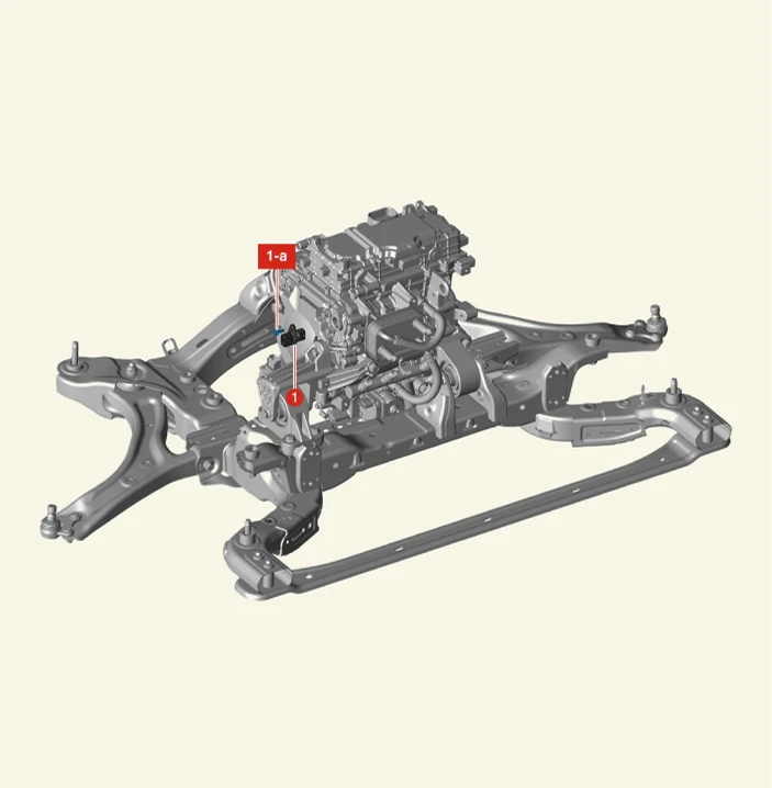
1. Motor Position and Temperature Sensor
1-a. 9.8 - 11.8 N·m (1.0 - 1.2 kgf·m, 7.2 - 8.7 lb·ft)
Rear Motor
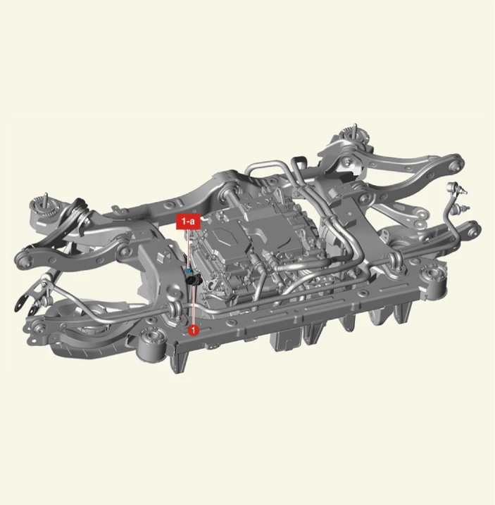
1. Motor Position and Temperature Sensor
1-a. 9.8 - 11.8 N·m (1.0 - 1.2 kgf·m, 7.2 - 8.7 lb·ft)
Removal

• When working on high voltage system, the work should be performed by technicians who have completed the relevant training. It is because that lack of knowledge of the high voltage system can lead to serious accidents due to electric shock or electric leakage.
• When working a high voltage system, the technician must be recognized and observe "General Safety Information and Caution". If do not follow, serious accidents like electric shock and short circuit are caused.
• When working on high voltage system, make sure to check the Personal Protective Equipment (PPE) and high voltage shut-off procedures.

• Use a fender cover to protect the painted surface.
• Be careful not to damage the connector when disconnecting.

1.Shut off the high voltage circuit.(Refer to Motor and Reduction Gear System - "High Voltage Shut-off Procedures")
2.Remove the front trunk.(Refer to Body - "Front Trunk")
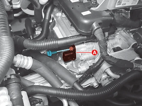
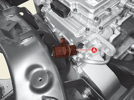
3.Disconnect the motor position and temperature sensor connector (A).
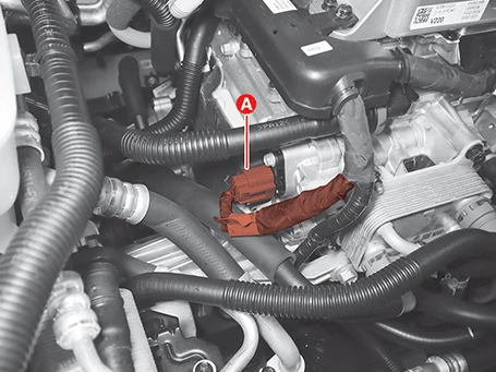
4.Remove the motor position and temperature sensor (A) after removing the mounting bolts.
Tightening torque :9.8 - 11.8 N·m (1.0 - 1.2 kgf·m, 7.2 - 8.7 lb·ft)
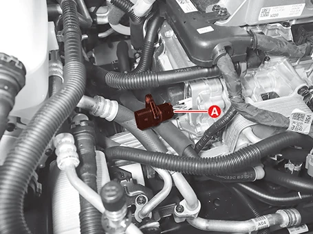
5.Remove the motor position and temperature sensor (A) after disconnecting the connector.
Installation
1.Install in the reverse order of removal.
Removal

• When working on high voltage system, the work should be performed by technicians who have completed the relevant training. It is because that lack of knowledge of the high voltage system can lead to serious accidents due to electric shock or electric leakage.
• When working a high voltage system, the technician must be recognized and observe "General Safety Information and Caution". If do not follow, serious accidents like electric shock and short circuit are caused.
• When working on high voltage system, make sure to check the Personal Protective Equipment (PPE) and high voltage shut-off procedures.

• Use a fender cover to protect the painted surface.
• Be careful not to damage the connector when disconnecting.

1.Shut off the high voltage circuit.(Refer to Motor and Reduction Gear System - "High Voltage Shut-off Procedures")
2.Remove the rear motor and reduction gear assembly.(Refer to Motor and Reduction Gear System - "Rear Motor and Reduction Gear Assembly")
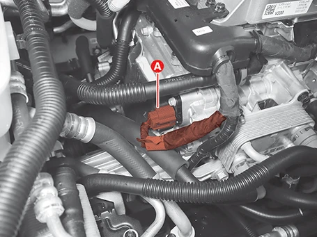
3.Disconnect the motor position and temperature sensor connector (A).
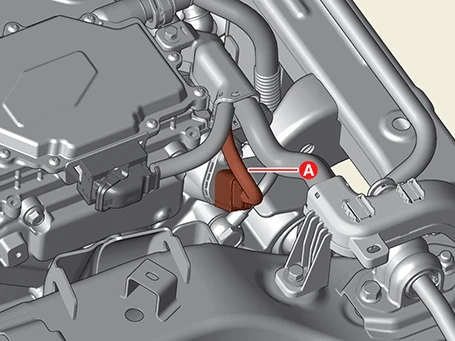
4.Remove the motor position and temperature sensor (A) after removing the mounting bolt.
Tightening torque :9.8 - 11.8 N·m (1.0 - 1.2 kgf·m, 7.2 - 8.7 lb·ft)
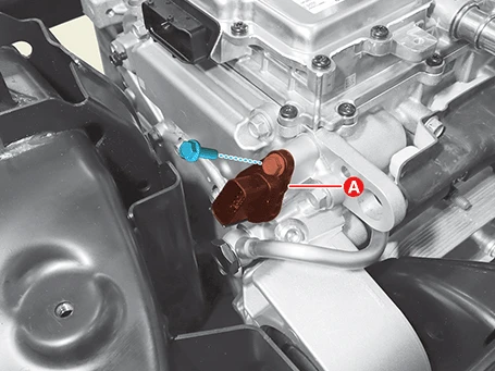
5.Remove the motor position and temperature sensor (A) after disconnecting the connector.
Installation
1.Install in the reverse order of removal.
Front Motor Position and Temperature Sensor Inspection

• When working on high voltage system, the work should be performed by technicians who have completed the relevant training. It is because that lack of knowledge of the high voltage system can lead to serious accidents due to electric shock or electric leakage.
• When working on high voltage system or related system, make sure that you are familiar and comply with the "Safety Precautions, Cautions and Warnings." If you do not comply with the instructions, serious accidents due to electric shock or leakage may occur.
• When working on high voltage system, make sure to check the Personal Protective Equipment (PPE) and high voltage shut-off procedures.
1.Shut off the high voltage circuit.(Refer to Motor and Reduction Gear System - "High Voltage Shut-off Procedures")
2.Remove the front trunk.(Refer to Body - "Front Trunk")
3.Remove the inverter assembly.(Refer to Battery Control System - "Inverter Assembly - 4WD")
4.Disconnect the motor position and temperature sensor connector (A).
5.Check the phase resistance using a multi tester.
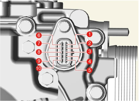
| Item | Inspection area | Specifications | Remark | |
| Motor temperature sensor | Phase resistance | Pin 5 - Pin 10 | 18.1 - 20.8 kΩ | Reference temperature : 20°C (68°F ) |
| Insulation resistance | Pin 5 - Motor housing | 100 MΩ or more | Apply DC 500 V for 5 seconds | |
| Pin 5 - Motor U/ V/ W | ||||
| Dielectric strength | Pin 5 - Motor housing | 0.5 mA or less | Apply AC 1,800v for 1 second | |
| Motor position sensor | Phase resistance | Pin 2 - Pin 7 | 16.6 Ω ±7% | Reference temperature : 20°C (68°F ) |
| Pin 3 - Pin 8 | 58.6 Ω ±7% | |||
| Pin 4 - Pin 9 | 49.8 Ω ±7% | |||
| Insulation resistance | Pin 2 - Motor housing | 100 MΩ or more | Apply DC 500 V for 5 seconds | |
| Pin 3 - Motor housing | ||||
| Pin 4 - Motor housing | ||||
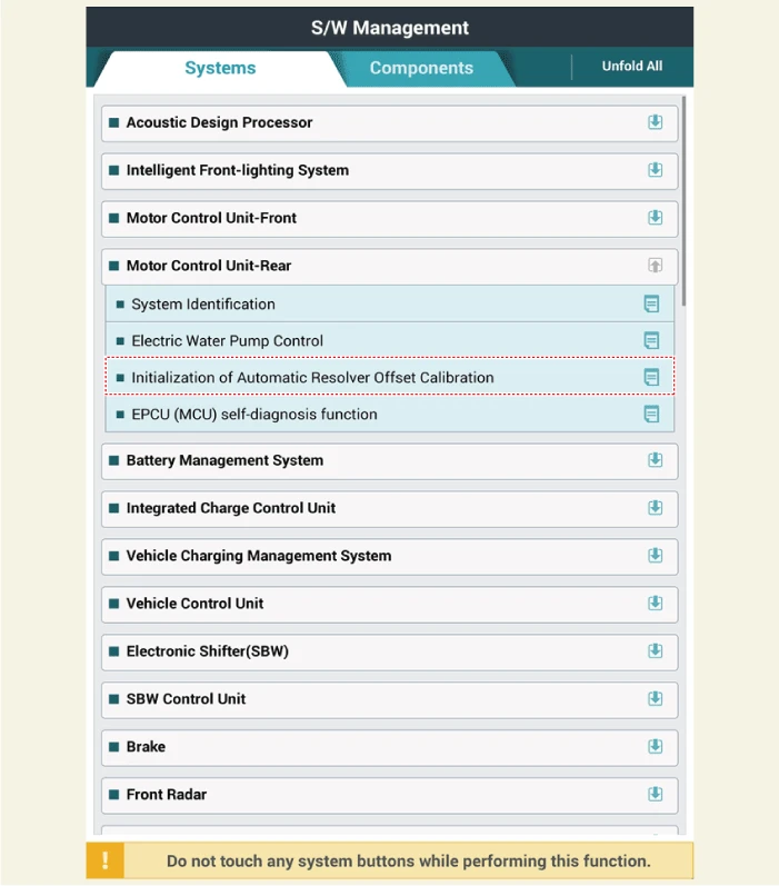
Initialization of Front Motor Resolver Offset Automatic Calibration
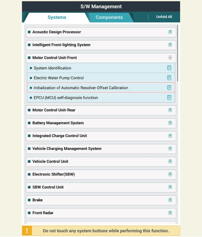
1.IG "OFF" and connect the KDS to the Data Link Connector.
2.P range & IG "ON" (Power button LED "Red"), Select "Vehicle S/W Management"
3.Perform the "Motor Control Unit-Front" and "Initialization of Automatic Resolver Offset Calibration" using the KDS.
Rear Motor Position and Temperature Sensor Inspection

• When working on high voltage system, the work should be performed by technicians who have completed the relevant training. It is because that lack of knowledge of the high voltage system can lead to serious accidents due to electric shock or electric leakage.
• When working a high voltage system, the technician must be recognized and observe "General Safety Information and Caution". If do not follow, serious accidents like electric shock and short circuit are caused.
• When working on high voltage system, make sure to check the Personal Protective Equipment (PPE) and high voltage shut-off procedures.
1.Shut off the high voltage circuit.(Refer to Motor and Reduction Gear System - "High Voltage Shut-off Procedures")
2.Remove the rear motor and reduction gear assembly.(Refer to Motor and Reduction Gear System - "Rear Motor and Reduction Gear Assembly")
3.Remove the multi inverter assembly.(Refer to Battery Control System - "Multi Inverter Assembly")
4.Disconnect the motor position and temperature sensor connector (A).
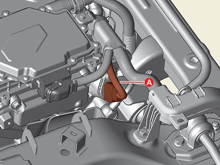
5.Check the phase resistance using a multi tester.
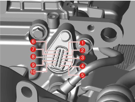
| Item | Inspection area | Specifications | Remark | |
| Motor temperature sensor | Phase resistance | Pin 5 - Pin 10 | 18.1 - 20.8 kΩ | Reference temperature : 20°C (68°F ) |
| Insulation resistance | Pin 5 - Motor housing | 100 MΩ or more | Apply DC 500 V for 5 seconds | |
| Pin 5 - Motor U/ V/ W | ||||
| Dielectric strength | Pin 5 - Motor housing | 0.5 mA or less | Apply AC 1,800 V for 1 second | |
| Motor position sensor | Phase resistance | Pin 2 - Pin 7 | 16.6 Ω ±7% | Reference temperature : 20°C (68°F ) |
| Pin 3 - Pin 8 | 58.6 Ω ±7% | |||
| Pin 4 - Pin 9 | 49.8 Ω ±7% | |||
| Insulation resistance | Pin 2 - Motor housing | 100 MΩ or more | Apply DC 500 V for 5 seconds | |
| Pin 3 - Motor housing | ||||
| Pin 4 - Motor housing | ||||
Initialization of Rear Motor Resolver Offset Automatic Calibration
1.IG "OFF" and connect the KDS to the Data Link Connector.
2.P range & IG "ON" (Power button LED "Red"), Select "Vehicle S/W Management"
3.Perform the "Motor Control Unit-Rear" and "Initialization of Automatic Resolver Offset Calibration" using the KDS.
